How Do You Choose an OEM Metal Parts Supplier?
2026-10-26
Outsourcing Custom Metal Parts: A Practical Guide to Machining Services
2026-10-28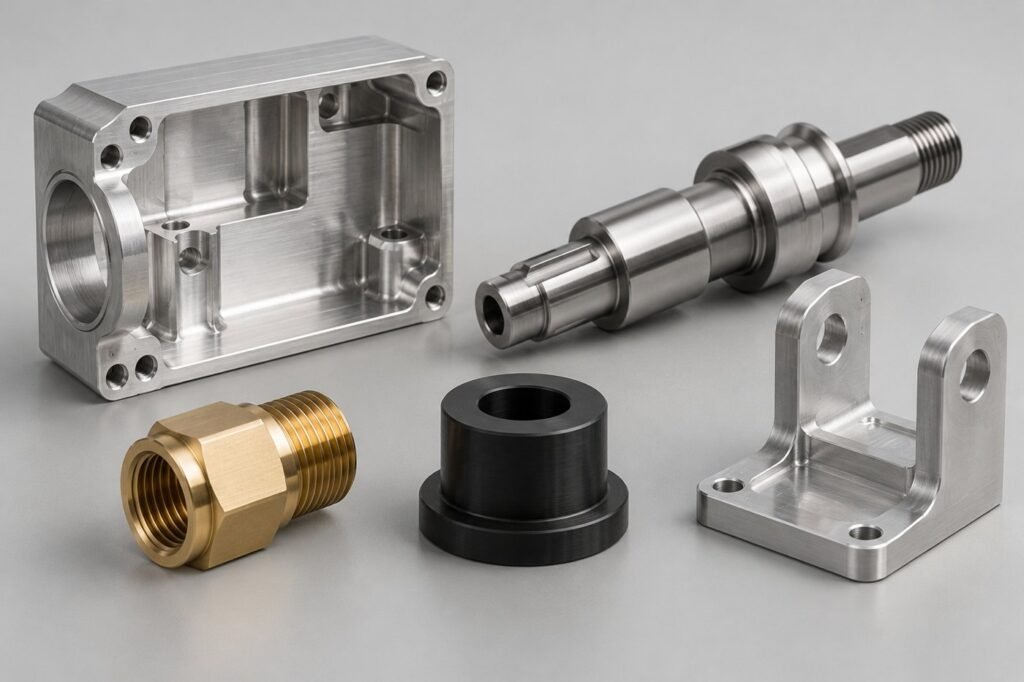
MILEMETAL · PRECISION MACHINING INSIGHTS
Precision Machined Parts: Processes, Materials, Tolerances & Quality
A shaft can look perfect and still refuse to slide into its housing. A bracket can match its outside dimensions yet put a sensor in the wrong position. Precision machining is about getting those working relationships right—and reproducing them when the next batch arrives.
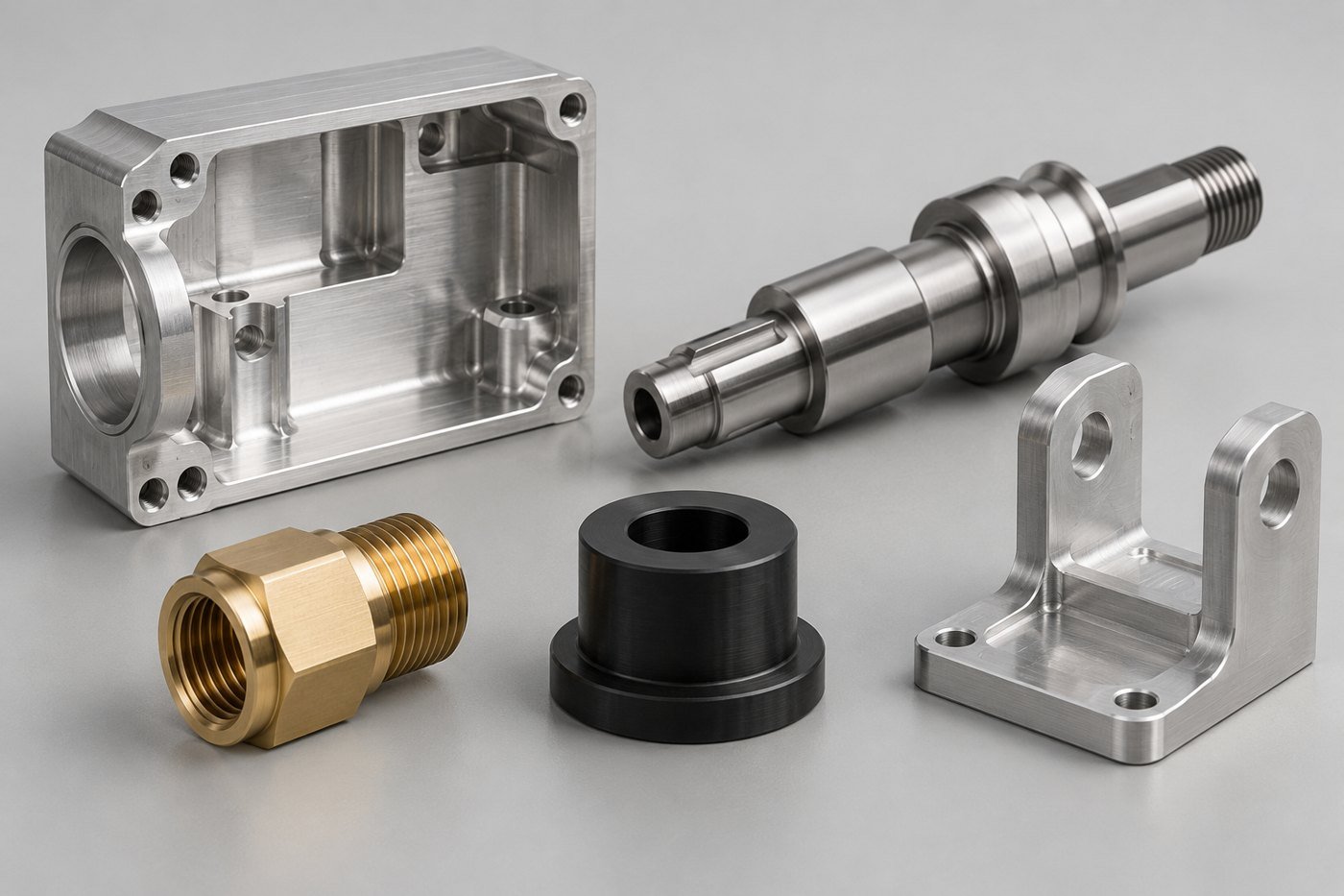
What makes a machined part “precision”?
Precision machined parts are components made to controlled dimensional and geometric requirements so they can perform a defined job. A simple spacer may need a closely controlled length. A complex housing may need its mounting face, bore and hole pattern to relate correctly to one another. Neither appearance nor complexity tells the whole story.
There is no single tolerance that makes every component a precision part. The important questions are which features control the assembly, what variation the design permits and how those features will be verified. A clearance hole does not need the same attention as a bearing seat simply because they appear on the same drawing.
In everyday manufacturing discussions, accuracy describes closeness to the intended value, while precision concerns consistency. A batch can be consistent and still be centered on the wrong size. For a purchasing decision, ask for evidence of conformance to the drawing as well as repeatability—not just a machine description or a photograph of a finely finished part.
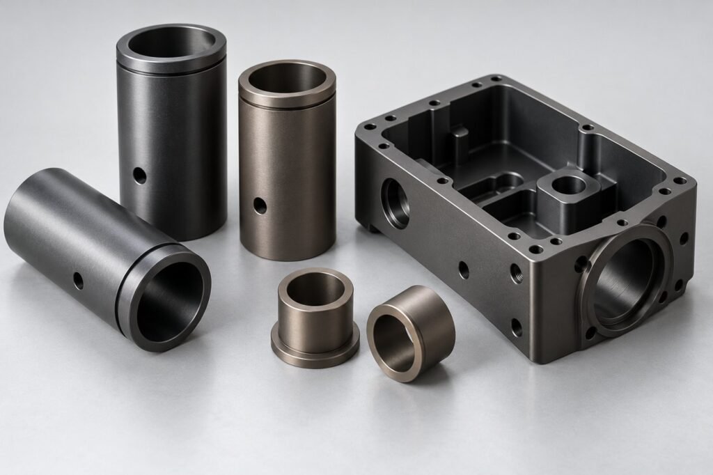
Six examples from the MileMetal product library
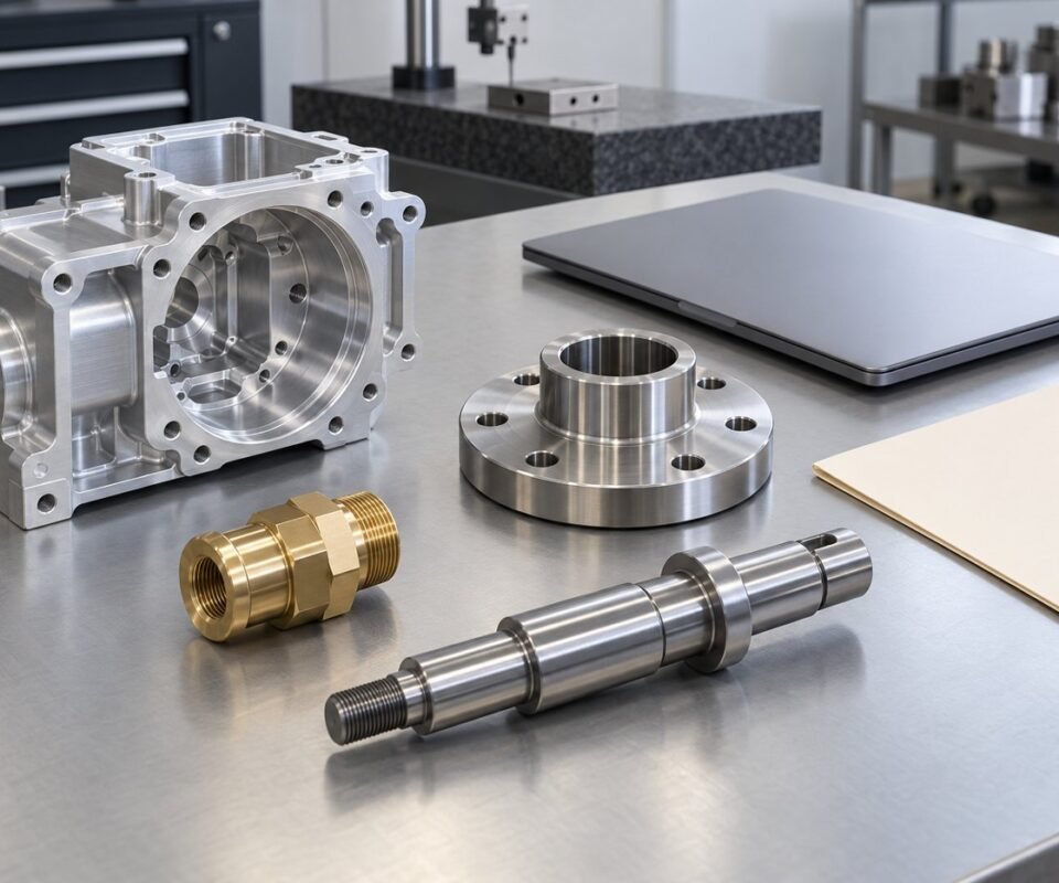
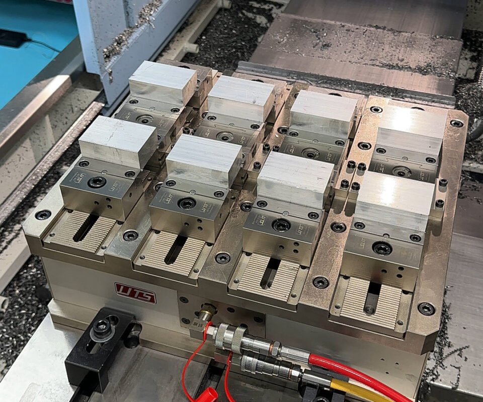
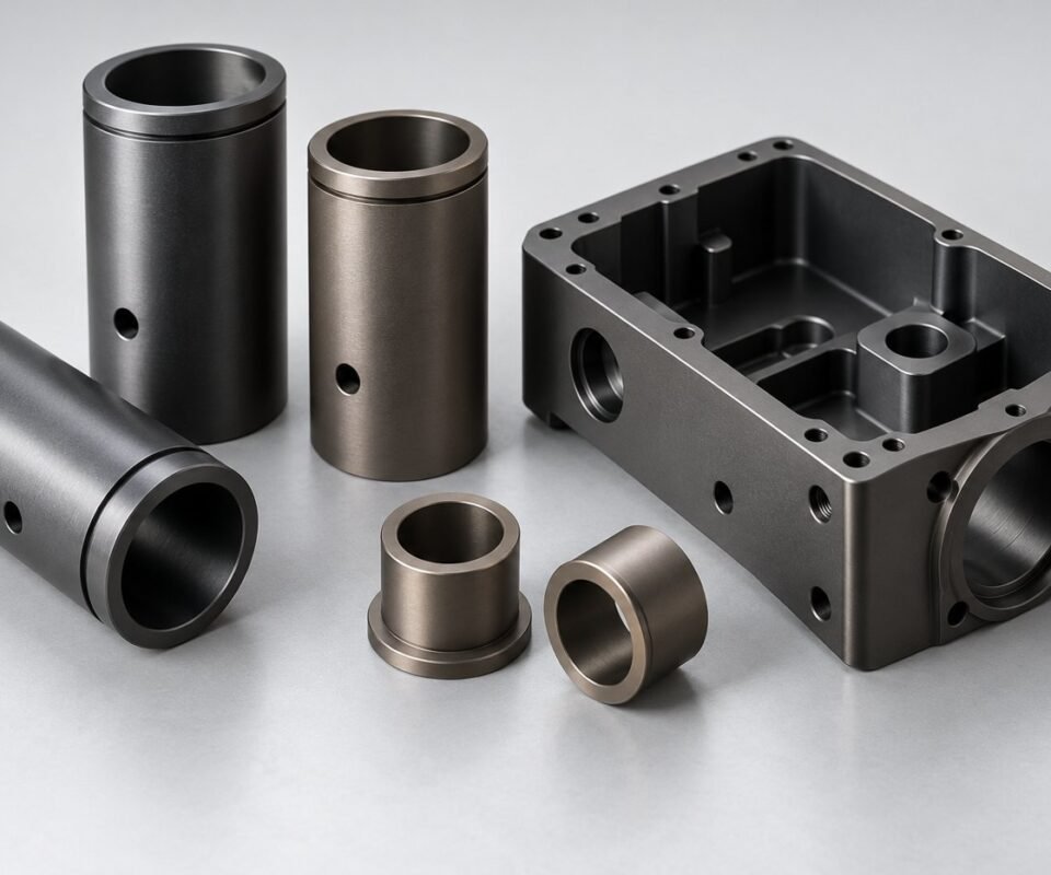
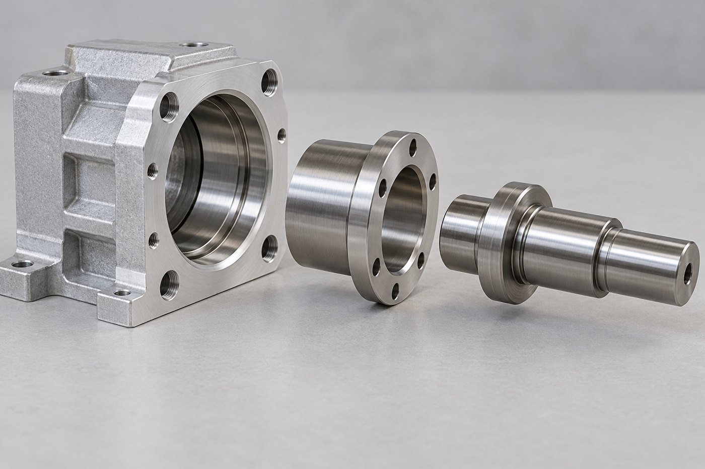
These photographs show different part forms rather than a single customer project. Each presents a different manufacturing question: how to support a shaft, reach a pocket, control a bore or preserve a small threaded feature.


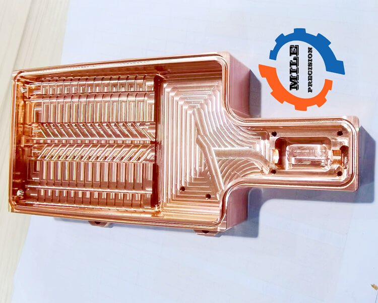
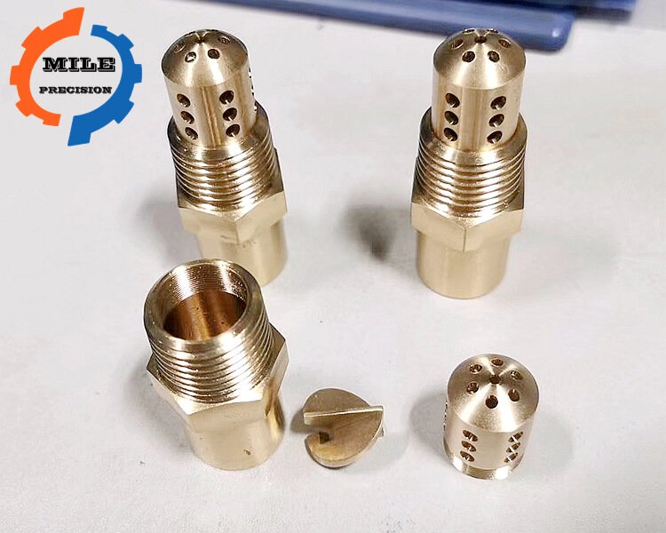
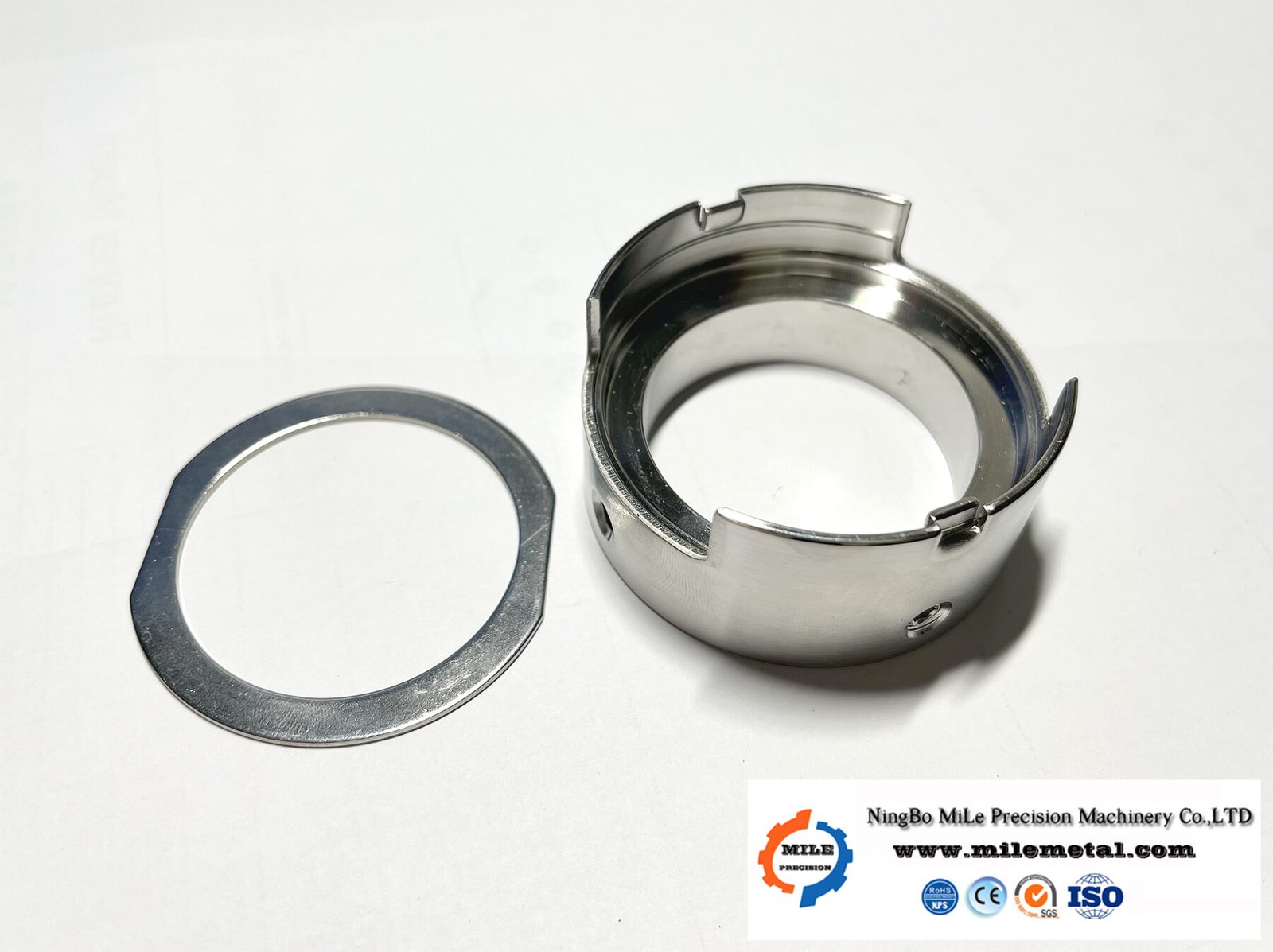
A useful enquiry connects the product image to a drawing. For example, identify whether the circular opening in a housing is a clearance feature, a locating bore or a sealing interface. The visible shape may be similar, but the machining and inspection plans can be quite different.
Choose the machining process around the features
Most precision components do not need every available machining technology. They need a route that gives the cutting tool access, supports the workpiece and preserves the relationships between important features. Sometimes that route is a straightforward turning operation. Sometimes it includes milling, heat treatment and a separate finishing step.
| Process | Where it is useful | What deserves attention |
|---|---|---|
| CNC turning | Shafts, sleeves, bushings, threaded adapters and other mainly rotational forms | Workpiece support, diameter relationships, shoulders and usable thread length |
| CNC milling | Housings, brackets, pockets, slots and mounting faces | Tool access, internal radii, wall stiffness and the relationship between setups |
| Drilling, boring and reaming | Holes with different size, location or finish requirements | The hole’s actual function, its depth, entry geometry and inspection access |
| Grinding | Selected surfaces that need a dedicated finishing operation, including some hardened components | Processing sequence, remaining stock, final geometry and surface condition |
| EDM, where appropriate | Selected conductive-material features that are difficult to reach or form with a rotating cutter | Process type, access, surface condition and any subsequent finishing |
This table describes process-selection considerations, not a statement that every operation is required or available for every MileMetal enquiry. The manufacturing scope is confirmed against the actual component.
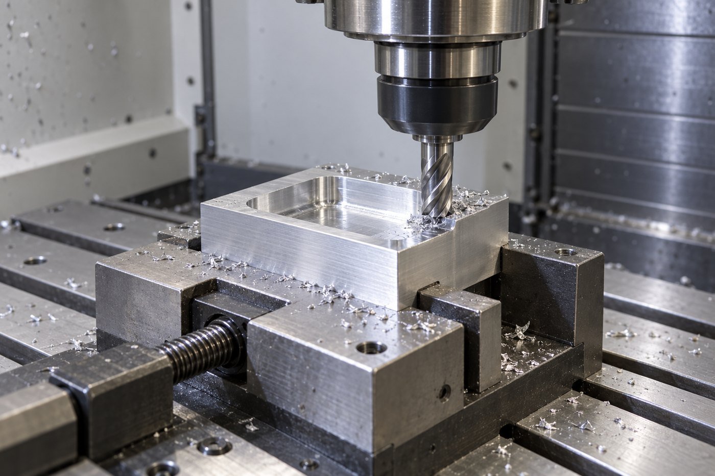
Why the number of setups matters
Each time a part is moved, the next operation needs a reliable way to locate it. A housing machined on several sides may look simple in CAD, but its bore and mounting face still need to share a meaningful reference. The process plan should explain how that relationship is maintained.
A multi-axis machine can offer access to more faces, but the machine name alone does not establish the finished result. Workholding, cutting strategy, tool condition and measurement still matter. Ask how the critical features will be made and checked rather than treating the number of axes as a quality score.
For mainly cylindrical components, our CNC turning guide explains the process in more detail.
How a drawing becomes a repeatable component
The first useful step is a drawing review. Before programming begins, the model and drawing should agree on the part revision, material, threads, critical dimensions and finish. Open questions are easier to resolve while the part is still a file.
Define the part and its interfaces
Review the CAD model, drawing and mating components. Identify the features that determine fit, alignment or sealing, and agree how they will be accepted.
Plan material and operations
Confirm the grade and condition, choose a suitable starting form and establish the sequence of machining and any secondary processing.
Prepare workholding and machining
Locate and support the part without hiding important features. Plan tool access, machining allowances and checks that are useful before the part leaves the setup.
Complete finishing requirements
Deburr, clean and carry out the specified surface or thermal processing. Keep masked areas and after-finish dimensions visible in the job requirements.
Verify the released definition
Measure the agreed characteristics against the current drawing. Record the results needed for the order, including the final condition of critical fits.
Protect and identify the parts
Keep sensitive surfaces separated during packaging and maintain part and revision identification so the receiving team knows what it is assembling.
For a prototype, this sequence may end with an assembly trial and a revision. For a repeat order, it should start from the approved files and the lessons already captured. Recreating that history from scattered messages is an avoidable source of confusion.
Material choice changes more than the cutting time
Begin with what the component must do. A housing, a wear sleeve and a conductive contact can share similar dimensions yet need very different materials. Include the exact grade and condition; a broad label such as “stainless steel” leaves important decisions unresolved.
| Material family | Typical reason to consider it | Information to include in the enquiry |
|---|---|---|
| Aluminum, such as a specified 6061 or 7075 grade and temper | Housings, supports and other components where mass is part of the design | Alloy, temper, structural requirements, visible surfaces and finish |
| Stainless steel, specified grade | Components selected for their service environment and mechanical requirements | Grade, exposure conditions, material condition and surface treatment |
| Carbon or alloy steel | Shafts, pins and other mechanical parts with defined strength or wear requirements | Heat treatment, hardness requirements, processing sequence and final sizes |
| Brass or copper, specified alloy | Selected fittings, electrical contacts, thermal components or decorative parts | Alloy, contact surfaces, plating and any application-specific restrictions |
| Engineering plastics, such as a specified POM, PA or PEEK grade | Guides, spacers, insulating parts and other applications suited to the selected polymer | Resin grade, temperature, loading, conditioning and dimensional requirements |
Do not substitute an apparently similar grade without reviewing the requirements it must satisfy. If alternatives are acceptable, state the restrictions that still apply. This makes a material discussion useful instead of turning it into a guess about which properties matter most.
Also explain whether the first parts represent production intent. A simplified material can be appropriate for some packaging checks, but it may not answer a question about wear, thermal behavior or the final surface treatment.
Give tight tolerances a specific job
A good tolerance communicates how much variation the design can accept. Making every value tighter does not automatically improve the product; it can add machining and inspection work to features that do not control performance. Protolabs’ tolerancing guidance likewise emphasizes defining requirements through the part model and drawing.
| Requirement | Illustrative callout | What it establishes |
|---|---|---|
| Linear size | 20.00 ±0.02 mm | A size interval from 19.98 to 20.02 mm for the identified feature |
| Unilateral size tolerance | 10.000 +0.020/−0.000 mm | An allowed size interval from 10.000 to 10.020 mm |
| Flatness | 0.03 mm on a designated face | A form requirement for that face; it does not by itself locate the face relative to another feature |
| Surface texture | Ra 1.6 µm on a marked surface | A texture requirement, separate from dimensional size and geometric form |
| Thread | M6 × 1–6H, 10 mm usable full thread depth | A defined internal thread and engagement length; drilled depth needs its own allowance |
These are examples of how requirements are expressed, not recommended values for a particular assembly or guaranteed MileMetal capabilities. Select tolerances from the design and confirm feasibility for the actual material, geometry, quantity and finish.
A simple fit example shows why the whole assembly matters
Suppose a design permits a shaft diameter of 19.98–20.00 mm and a bore diameter of 20.02–20.04 mm. The smallest possible diametral clearance is 20.02 − 20.00 = 0.02 mm. The largest is 20.04 − 19.98 = 0.06 mm. Whether that range is suitable depends on the mechanism; it is not established by the arithmetic alone.
That example also shows why inspecting only the nominal sizes is insufficient. Both parts can pass their individual limits while producing very different clearances. Include the mating-part information when fit is the reason for a close tolerance.
Location is a different question from size
A hole can be the correct diameter and still be in the wrong place. Define the reference faces or axes that explain how the part is located in the assembly. Where geometric tolerances are used, identify the governing drawing standard and make the datum system consistent with the design.
Keep the CAD model and drawing at the same revision. If they disagree, resolve the conflict before production rather than expecting the supplier to choose the intended definition.
Design details that make precision easier to achieve
Many manufacturing difficulties begin with a feature that is easy to draw but difficult to reach, support or measure. A brief review can reveal those issues without changing the product’s purpose.
Leave room for the tool
Internal corners, deep pockets and small openings determine which tools can enter the part. A rounded internal corner is a natural consequence of machining with a rotating cutter. If a sharp corner is functionally necessary, flag it early so an appropriate route can be considered.
Deep features can require longer tools and more demanding setups. Sandvik Coromant’s milling application guide discusses overhang and vibration as related process concerns. On a drawing review, the useful question is whether a small access change would allow a more stable operation.
Consider how the part will be held
A thin wall or slender shaft may need support during machining. Ask which surfaces can serve as locating or clamping areas, especially if most faces are cosmetic or functional. Avoid hiding this question until the component is already scheduled for production.
Finish the edges deliberately
“Remove burrs” is helpful, but it does not define every edge. Specify radii or chamfers on handled edges and mating entries where their shape matters. Give particular attention to cross-holes, intersecting passages and features that are difficult to inspect visually.
Make the critical features measurable
A design can contain a requirement that is difficult to verify on the finished component. Discuss measurement access and acceptance conditions before manufacture. This is especially useful for internal geometry or features that become hidden after assembly.
Surface finishing belongs in the machining plan
A part should be evaluated in the condition in which its dimensions are specified. If a bore must fit after anodizing, that requirement needs to be considered before the bore is machined. If a contact face must remain uncoated, it needs a clear masking instruction.
Mark cosmetic surfaces separately from functional ones. An appearance reference can help explain a visible finish, while mating faces and sliding surfaces need defined technical requirements. A general request for a smooth finish does not tell the supplier which question is more important.
Where the drawing calls for heat treatment, plating or another secondary operation, agree on its place in the manufacturing route and when the critical dimensions are measured. Do not assume a size checked before processing is the same as the accepted final size.
For aluminum parts, our Type III anodizing design guide explains coating-related dimensional considerations. Components with sliding interfaces may also benefit from reviewing the hardcoat and PTFE treatment guide.
What useful inspection evidence looks like
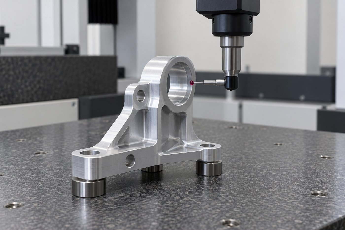
An inspection report is most useful when a reader can connect each result to a requirement on the drawing. It should identify the part and revision, the characteristic, the acceptance limits and the measured result. The method must be suitable for the feature being checked.
| Feature or concern | Possible inspection approach | What to agree |
|---|---|---|
| External size | A suitable micrometer or other dimensional instrument | Measurement locations, final condition and required reporting |
| Bore size | A suitable bore gauge, plug gauge or coordinate measurement | Size limits, access and whether variable readings or pass/fail results are needed |
| Feature location and geometry | CMM or another method appropriate to the requirement | Datums, alignment, sampling strategy and drawing interpretation |
| Thread acceptance | Specified thread gauging and depth verification | Thread designation, usable depth and acceptance condition |
| Surface texture | Suitable surface texture measurement | Marked area, measurement settings and before/after-finish condition |
| Visible finish and edge condition | Defined visual review and any agreed sample comparison | Visible faces, viewing conditions, reference and allowed variations |
A digital display with many decimal places is not enough to establish confidence in a measurement. NIST’s measurement uncertainty overview explains why a result needs to be considered with its uncertainty. For a close acceptance limit, discuss the measurement method and decision rule rather than relying only on the displayed resolution.
Be clear about inspection coverage. A first-piece report, a sampled batch report and 100% inspection are different deliverables. Specify what is needed for the order, and avoid treating a report on one part as proof that every part was measured.
For repeat production, changes to the drawing, material or finishing route may justify a fresh review of the inspection plan. The goal is to preserve the evidence that matters to the assembly, not simply repeat an old checklist.
How to control cost without losing the precision you need
Begin by separating essential requirements from preferences. Keep close control on the features that locate, seal or move against another component. Allow nonfunctional surfaces the variation that the design can accept. This gives the manufacturer room to choose a practical route without weakening the important interfaces.
Other useful discussions include tool access, the number of setups, material form, finishing requirements and inspection coverage. Order quantity matters too: a route that makes sense for a development sample may not be the best choice for a repeat batch. Share expected demand as a range if the exact volume is not yet known.
Compare quotations against the same released file set. Check whether material, secondary processing, required reports and packaging are included. A lower price is difficult to assess when one quotation includes the finished and inspected component and another covers only machining.
Where precision machined parts fit into real products
Electronics and instrumentation
Enclosures, connector supports and mounting plates must agree with the board layout and the surrounding assembly. Connector clearance and cover access can be as important as a close fit.
Automation and robotics
Gripper fingers, fixtures and mounting brackets depend on consistent location and practical replacement. Identify the surfaces that establish the working position.
Industrial equipment
Shafts, sleeves and housings connect components made by different suppliers. Mating geometry and service access help explain what the machining must achieve.
Product development
Prototype components turn a model into an assembly that can be checked. Tell the supplier what the build needs to prove, then capture approved changes before the next order.
What to send with your request for a quote
A useful quotation package includes a STEP model, a dimensioned drawing, the material and condition, quantity, finish and delivery target. Add the required inspection records and identify the dimensions that apply after finishing.
If the part mates with a purchased bearing, connector or other component, include the relevant interface information. If it is a replacement, distinguish intended dimensions from wear or field modifications. If it is a prototype, explain the next question you want the physical part to answer.
With that information, the discussion can focus on the component itself: its critical features, a suitable manufacturing route and any decisions that need to be closed before production.
Frequently asked questions
What is the difference between CNC machining and precision machining?
CNC describes computer-controlled machine operation. Precision machining describes the controlled result required by the part. CNC equipment can be part of that process, but the drawing, setup and inspection still determine whether the component meets its requirements.
What tolerances can be achieved?
Feasibility depends on the feature, size, material, geometry, process and final surface condition. Provide the actual drawing for review rather than applying a single advertised tolerance to every part.
Do I need a drawing if I already have a 3D model?
A model describes geometry, but the drawing communicates tolerances, threads, surface requirements and inspection notes. Use matching revisions and resolve any conflict between the files before manufacture.
Can plastic components also be precision machined?
Yes, when the selected material and process can meet the requirements. Specify the polymer grade and the conditions in which the part is used and measured rather than assuming all plastics behave alike.
Does a finer surface finish always improve a part?
The finish should serve the application. Define the surfaces that need a particular texture or appearance, and keep that requirement separate from size, flatness and other geometric controls.
Should I order prototypes before a production batch?
A first build is useful when fit, access or another design question remains open. Use the evaluation to approve the definition, then release any changes before ordering more parts.
What should I ask a precision machining supplier about quality?
Ask how the critical features will be made, how they will be measured and what records will accompany the order. Clarify the inspection coverage and final condition of the parts.
Let’s review the features that matter to your part
Send MileMetal your model, drawing and production requirements. We can review the machining scope, discuss critical interfaces and identify the details needed for a clear quotation.