
MILEMETAL · UAV COMPONENTS
CNC Machining for UAV Components
Bring the mechanical details of your civilian UAV project into focus. MileMetal reviews custom motor mounts, payload brackets, electronics housings, spacers and other drawing-defined components for development and production enquiries.
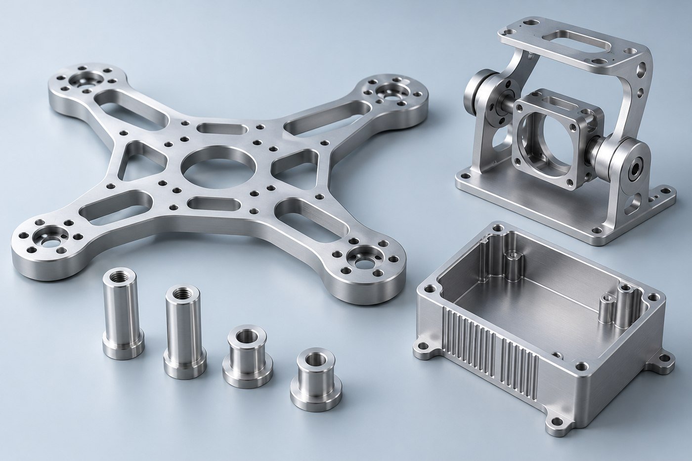
Design the component around the equipment it carries
A compact UAV assembly leaves little room for an interface to be almost right. Mounting patterns, connector clearance and access to fasteners all need to work within the same space. A useful machining brief shows how the component connects to the motor, payload, frame or electronics around it.
Share the component model, drawing and the relevant mating geometry. Explain whether the order supports packaging checks, a functional development build or a released design. This helps separate the dimensions that need close control from clearances that simply need to accommodate the surrounding assembly.
Define the motor interface without guessing from the exterior shape
A motor mount is governed by its mounting pattern, locating features and the space required for fasteners and cables. Provide the actual interface information from the selected equipment rather than relying on a generic motor outline.
If the part includes pockets or thin sections, make their purpose clear. Mass targets and structural requirements belong to the design brief, while the machining review considers how the specified geometry will be made and inspected. Any proposed change should be evaluated by the design team before it is released.
Define the finished condition of close fits when coating is required. Mark functional contact areas separately from cosmetic surfaces, and make sure the drawing states the usable depth of threaded holes in compact sections.
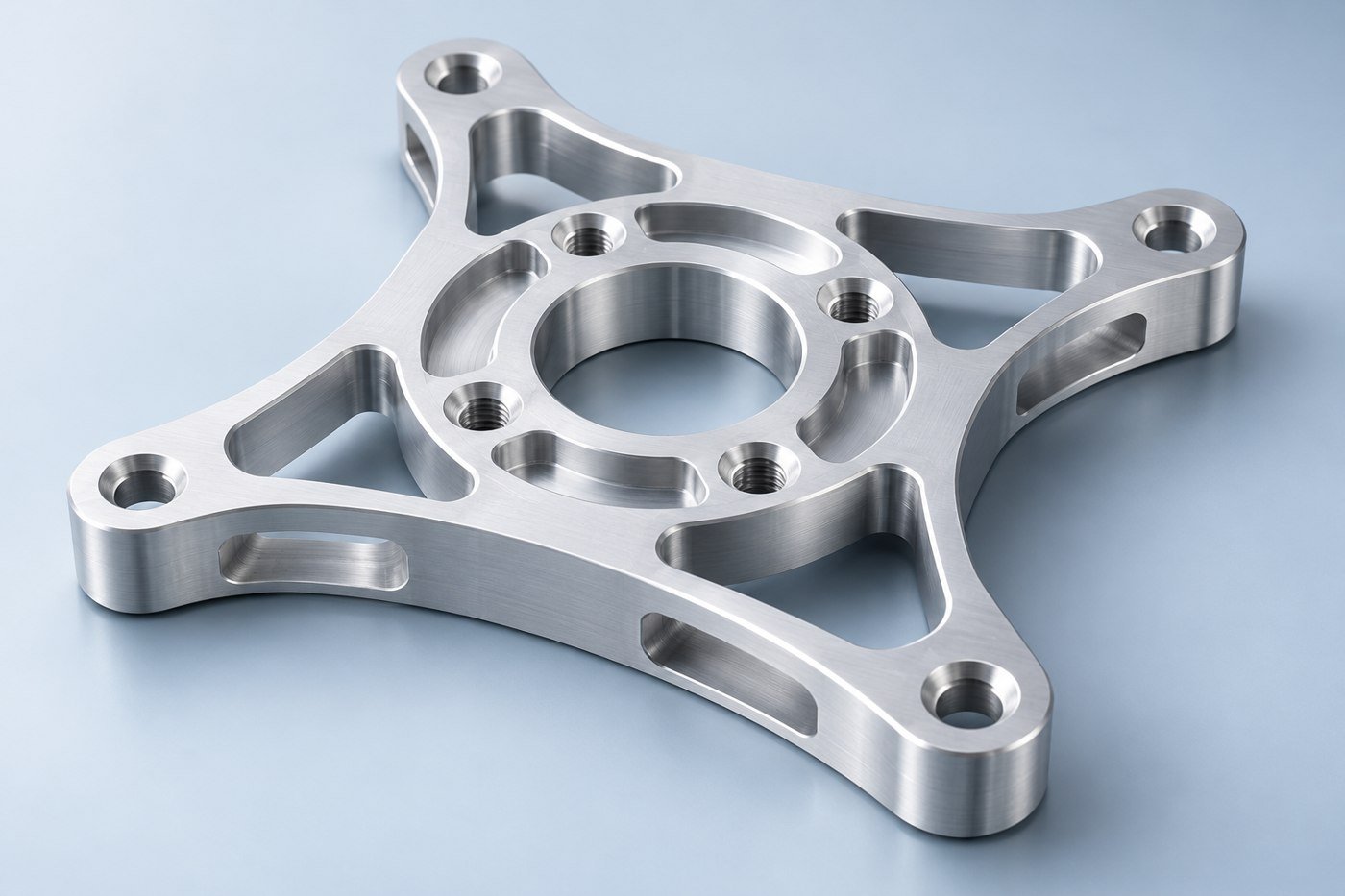
FROM THE MILEMETAL MEDIA LIBRARY
Part forms and the work behind them
These existing product and workshop photographs show relevant geometries and manufacturing activities. They are separate examples, rather than a single customer project.
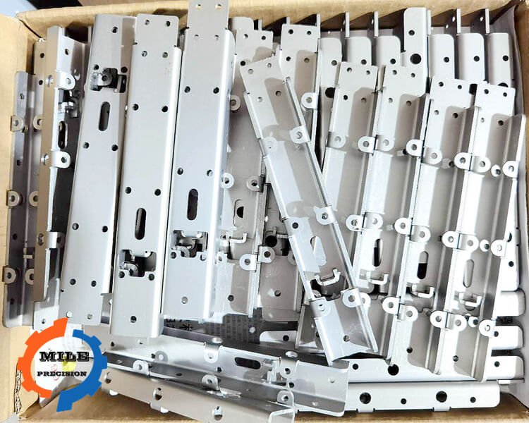
Lightweight component batch
A group of elongated metal components with pockets and mounting features.
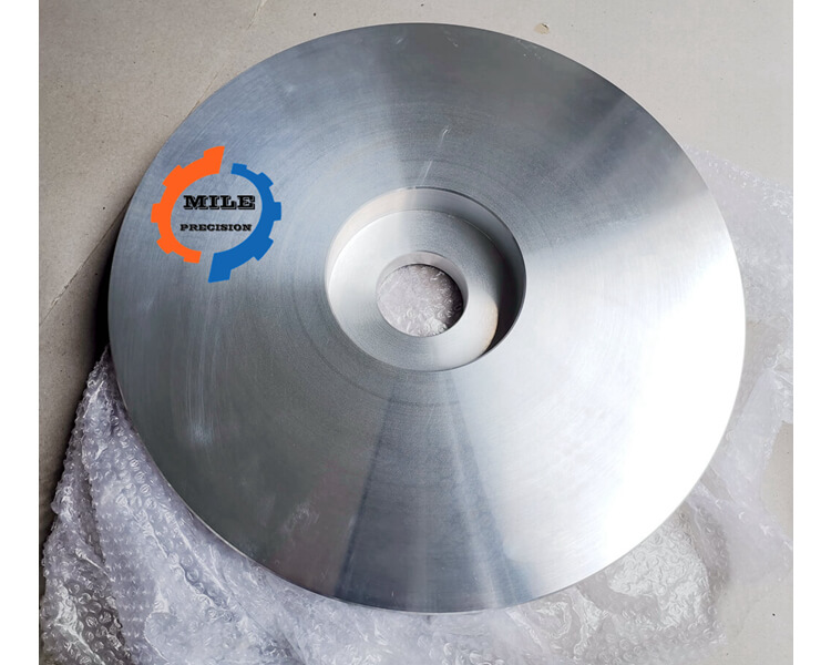
Turned circular component
A circular metal component with a central bore and shallow stepped face.

Circular plate geometry
A broad circular plate with a central opening.

Complex machined frame
An open machined frame with pockets and a large curved section.

Open mounting bracket
A bracket with an open center and multiple mounting holes.
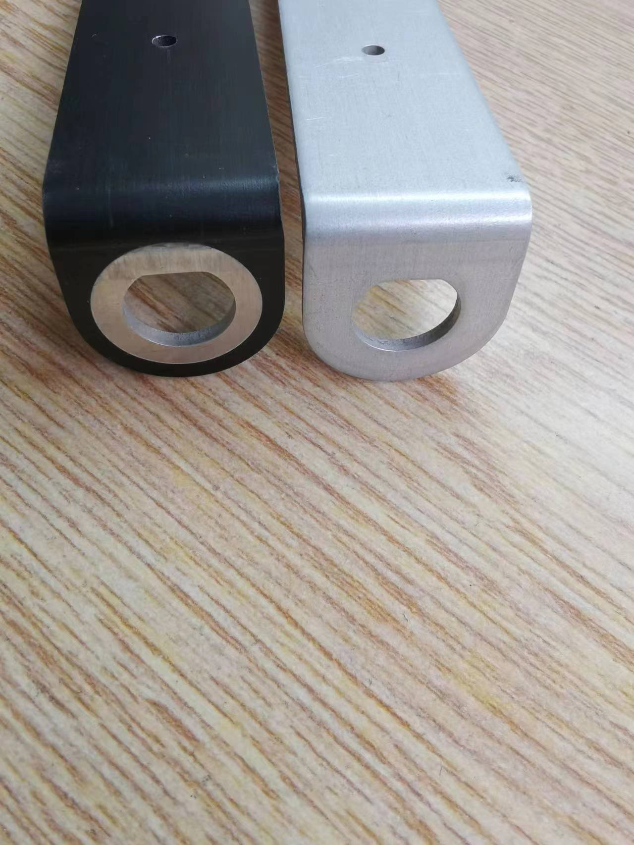
Finished component pair
Two compact metal components showing contrasting surface finishes.
Where these components fit
Motor and frame interfaces
Mounts, adapters and spacers connect selected equipment to the airframe. Include the actual mating pattern, fastener information and finished fit requirements.
Civilian camera and instrument payloads
Brackets, mounting plates and gimbal-related components need defined alignment and service access. Show payload interfaces and clearance envelopes.
Electronics packaging
Housings, covers and internal supports bring board, connector and mechanical layouts together. Identify contact faces, sealing details and assembly constraints.
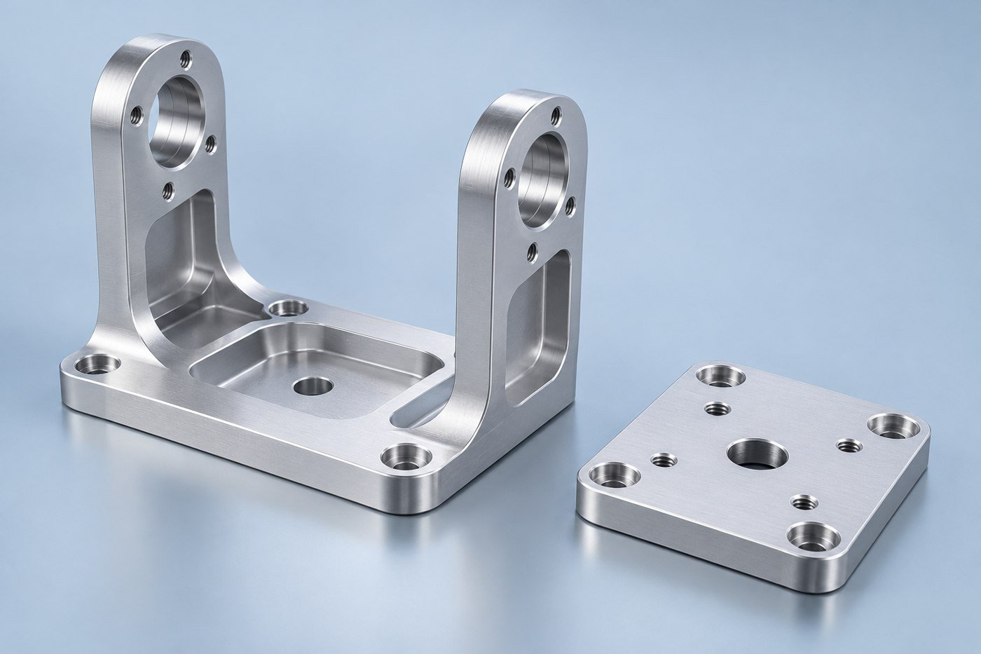
Keep the payload interface and service access in the same view
Camera and instrument mounts may need precise location while still allowing removal for adjustment or servicing. Show the locating features and explain which dimensions control alignment. Include the space needed for a tool and for the connector or cable to move during assembly.
For a gimbal-related bracket, provide the mating parts and the required positional relationships. A component drawing should make clear what is fixed, what provides clearance and what is adjustable. Do not ask the manufacturer to infer these roles from a rendered assembly image.
The finished UAV’s vibration behavior and payload performance depend on the complete system. Supply the component requirements derived from your design and use the assembled development build to evaluate the resulting behavior.
Choosing the material and finish
Use the material chosen for the component’s mechanical and environmental requirements. A lower part mass alone is not a complete material specification. Include alloy, condition, finish and any restrictions that the engineering evaluation depends on.
| Material to discuss | Typical component enquiry | Details to include |
|---|---|---|
| Aluminum 6061 or another specified alloy | Mounts, housings and general mechanical interfaces | Specify temper, finish, critical fits and any mass requirement. |
| Aluminum 7075, when selected by the designer | Drawing-defined structural components | Include material condition, processing restrictions and acceptance criteria. |
| Stainless or alloy steel, specified grade | Pins, shafts, inserts and selected interfaces | Define material condition, finish and mating geometry. |
| Engineering polymer, specified grade | Spacers, guides and selected insulating components | Include loading, temperature, dimensional and material restrictions. |
Material availability and process scope are confirmed against your drawing and quotation. Include any restrictions on substitutions or approved sources.
The drawing details worth resolving early
Use the component’s function to decide what needs close control. The following details give the machining and inspection review a useful starting point.
| Feature | What to define | Why it helps |
|---|---|---|
| Equipment mounting | Verified mating pattern and locating features | Matches the selected motor, payload or frame interface. |
| Threaded feature | Designation, usable depth and edge distance requirements | Makes compact fastening details explicit. |
| Alignment datum | Reference faces and positional relationships | Connects measurement to the payload or mounting function. |
| Coated fit | Finished dimensions and masking notes | Prevents uncertainty at close mechanical interfaces. |
| Development revision | Matching released files and evaluation purpose | Keeps the manufactured part tied to the build being assessed. |
Give the electronics room to assemble and breathe within the design
A compact electronics housing needs a realistic board envelope, connector positions and cover clearance. Include standoffs, screw access and cable routing in the review. A lid that fits the empty housing may still be difficult to install once the electronics are in place.
Where the housing participates in the thermal design, identify the actual contact surfaces and any interface material. If environmental protection is needed, define the seal and connector interfaces rather than assigning an enclosure rating to the bare machined component.
After a first assembly, record changes to mounting positions and clearances in the released file set. Keeping those revisions controlled makes later component batches easier to compare with the evaluated design.
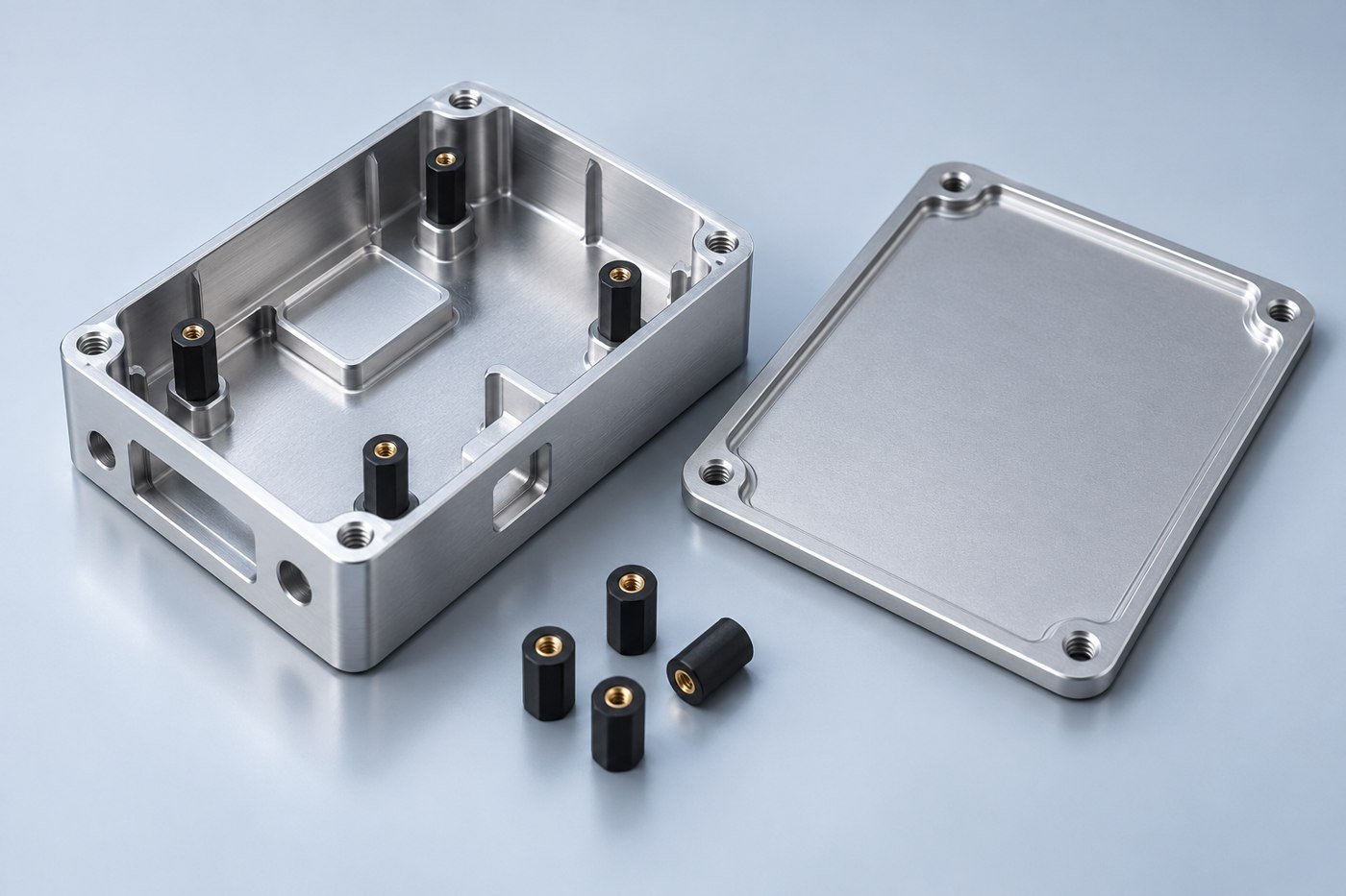
Inspection that follows the function of the part
Identify the dimensions that control alignment and assembly before ordering. Measurements should reference the same datum scheme used in the design, with the final surface condition included where it affects the fit.
A component inspection report describes the part supplied; it does not qualify the complete aircraft for flight. Any required airworthiness, system testing or project-specific qualification should be defined and managed within the UAV development program.
Put numbers where they help the drawing
Clear callouts are easier to quote and inspect than a general request for “high precision.” The examples below show the format of a requirement, not recommended design values or a guarantee of machining capability.
| Characteristic | Illustrative format | Complete the definition |
|---|---|---|
| Critical size | 25.00 ±0.05 mm | Identify the feature and the condition in which it is accepted. |
| Surface texture | Ra 1.6 μm on a marked face | Define the area and any measurement requirements. |
| Flatness | 0.05 mm over a designated face | State the support condition and whether acceptance follows finishing. |
| Thread | Full designation, class and usable depth | Include blind-hole clearance and the required finished condition. |
Where the design depends on a purchased bearing, connector, motor or other mating part, include that interface information. It is usually more useful than tightening unrelated dimensions across the entire component.
A straightforward way to start
Send a STEP model and a dimensioned drawing with the material, finish, quantity and delivery needs. Add an assembly view when it explains a fit or an access constraint. We can then review the component and identify the open details needed for a quotation.
Before production, agree on the released revision, any secondary operations and the inspection records to be supplied. After a first build, keep approved changes in the same controlled file set. This gives the next order a clear starting point instead of a trail of disconnected notes.
Questions before your first order
Can you quote custom civilian UAV mounts?
Send the component model and drawing, selected material, quantity and mating interface information. Include finish and inspection requirements.
Can you help reduce component weight?
Share the mass target and design constraints for manufacturing discussion. Structural changes require evaluation and approval by the design team before production.
What should I provide for a camera bracket?
Include the payload mounting interface, alignment requirements, cable envelope and access needed for installation or servicing.
Can UAV parts be anodized?
Specify the finish, color if relevant, masked areas and whether close-fit dimensions apply after finishing. The processing scope will be confirmed with the quote.
Does a machined enclosure have an ingress rating?
The rating belongs to a defined assembled product and its test conditions. Provide the component sealing requirements and specify any assembly or testing scope separately.
What documentation should accompany a repeat order?
Use the released part number and revision with matching CAD and drawing files, material and finish requirements, and the agreed inspection records.
START A CONVERSATION
Let’s discuss your uav components components
Share your drawing package and tell us which parts you need first. Include the features that matter to the assembly so the quotation can address the work you actually need.