
PRECISION PARTS FOR THERMAL SYSTEMS
CNC Machining for AI & Data Center Cooling Components
Custom CNC machined parts for the hardware behind AI liquid cooling: cold plate bases, coolant manifolds, precision fittings and mechanical interfaces. Work with MileMetal to turn your component drawings into a clear manufacturing plan, from the first evaluation parts to repeat production.
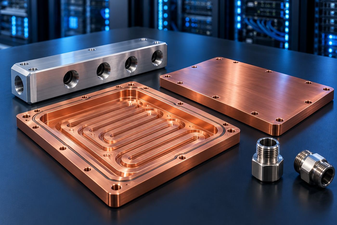
FROM THE HEAT SOURCE TO THE COOLANT CIRCUIT
Custom parts for your cooling assembly
A thermal assembly combines heat-transfer surfaces, fluid connections and mechanical supports. Submit individual components or a complete drawing package so the quotation can define the manufacturing scope clearly.
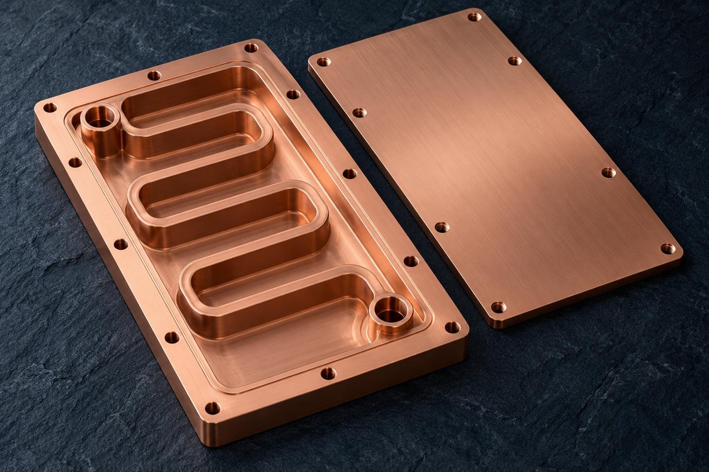
Concept illustration for reference only.
Cold plate bases & covers
Open coolant channels, contact faces, perimeter lands and mounting features reviewed together. Specify the lid-joining method and the condition in which flatness will be accepted.
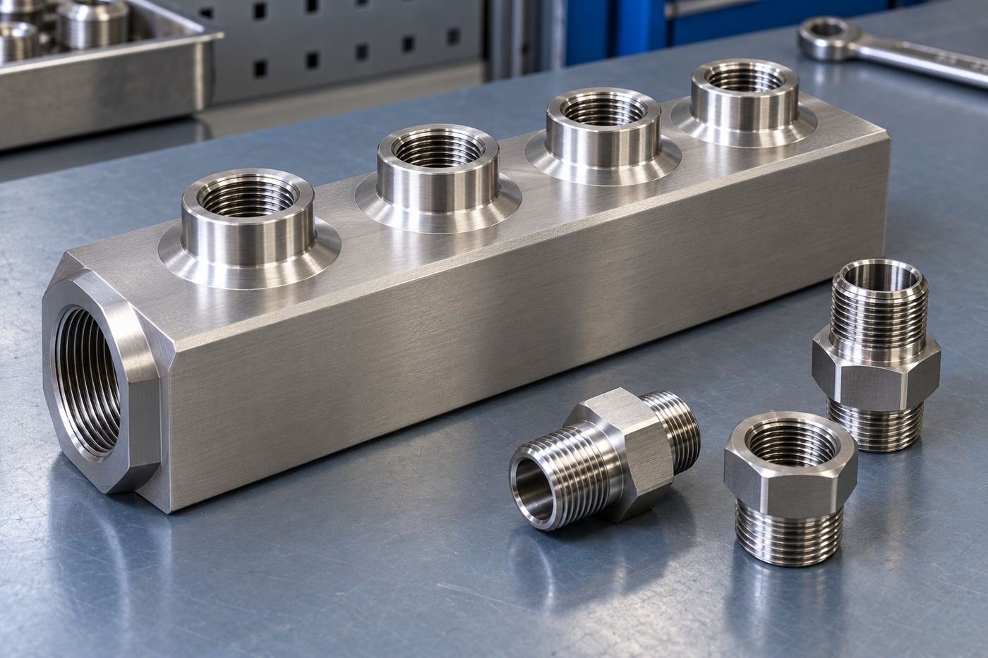
Concept illustration for reference only.
Coolant manifolds & adapters
Header passages, branch ports, closures and fitting interfaces. The review covers cutter access, intersecting passages, burr removal and assembly clearance.
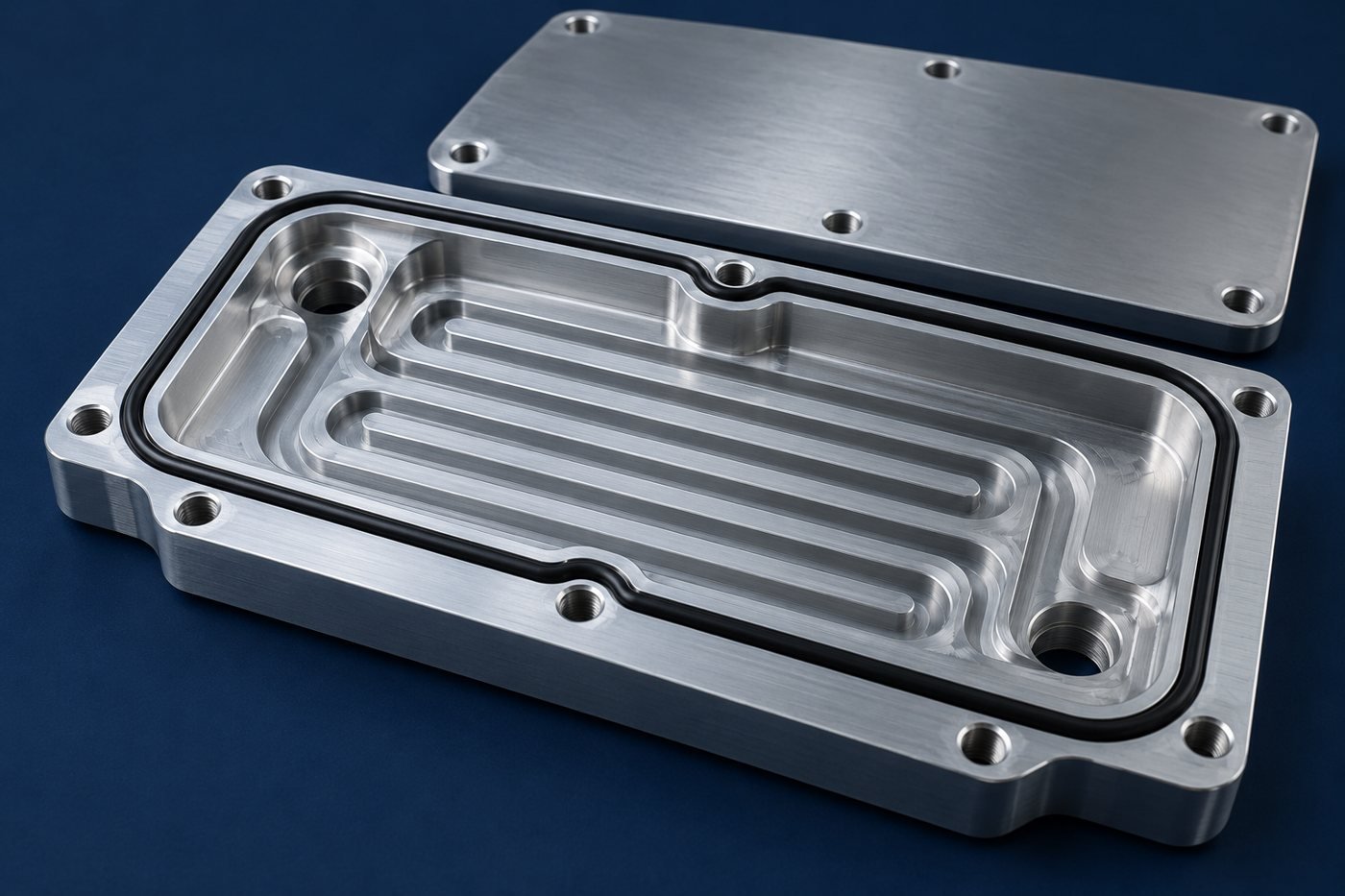
Concept illustration for reference only.
Seal interfaces & mechanical parts
Grooves, port faces, brackets, standoffs and housings made to the approved component definition. Identify which features locate, seal or carry mounting loads.
Turned connectors & port adapters
Custom bodies, threaded adapters, sleeves and retaining features connect the machined component to the coolant loop. Drawings should define the thread, seal seat, mating diameter and engagement length as a complete interface.
For quick-disconnect hardware, supply the approved mating geometry and functional requirements. A machined body alone is not a qualified, interchangeable coupling.
Housings, brackets & standoffs
Mounting frames, covers, sensor brackets and spacer sets locate cooling hardware within server and distribution assemblies. Review component mass, fastener access, cable routing and hose clearance together.
Identify cosmetic surfaces separately from functional datums so finishing and handling requirements remain practical.
Prototype parts & test fixtures
Evaluation plates, interface coupons and assembly fixtures help teams resolve fit, sealing and access before committing to a repeat order. Mark which prototype details must match the intended production design.
Keep material, joining and surface conditions representative when the prototype will be used for thermal or hydraulic validation.
WHERE THE PARTS FIT
Machined hardware across the liquid-cooling loop
The requirements change as coolant travels from distribution equipment to the heat source. Defining a component’s position in the assembly helps focus the review on the interfaces that matter.
Direct-to-chip cooling modules
Cold plate bases and covers sit close to CPUs, GPUs and other high-load devices. Priorities include contact-face geometry, fastener patterns, package clearance and the relationship between channel depth and remaining wall thickness.
Provide the interface drawing, thermal interface material arrangement and mounting condition. The system designer establishes the heat load and thermal acceptance criteria.
Multi-device cooling assemblies
Connector locations, mounting heights and service access must work across several cooled devices. A dimensionally correct individual part can still create assembly problems if the surrounding envelope is missing.
Include keep-out zones and mating CAD when requesting a review of brackets, interconnect blocks or multi-port plates.
Supply and return manifolds
Branch spacing, intersecting bores, end closures and fitting access shape the machining route. Long passages also create cleaning and inspection considerations that should be resolved before production.
Specify port identification, installation orientation and the features used to locate the manifold in its rack assembly.
CDU and fluid-control interfaces
Coolant distribution units can include custom adapter blocks, instrument mounts and mechanical supports. Review sensor insertion depth, threaded interfaces, wetted materials and access for maintenance.
Define whether the order covers individual machined parts, finishing or additional assembly operations so the quotation matches the equipment build plan.
ENGINEERING BEFORE CUTTING
Review the features that determine assembly performance
Channel access
Channel width alone does not establish machinability. Depth, internal radius, cutter reach, fin stiffness and inspection access all influence the route.
Contact & sealing faces
Separate dimensional tolerances, flatness and surface texture. Identify the functional area and whether acceptance follows joining, coating or final assembly.
Ports & assembly
Define the entire connection, including thread standard, seal arrangement, engagement and wrench clearance. Review neighboring parts and hose forces.
Project-specific tolerances and feature sizes are confirmed during drawing review. Machined geometry alone does not establish thermal capacity, pressure rating or leak performance.
MATERIALS & MANUFACTURING
Choose materials around the complete cooling assembly
Thermal performance is one part of the decision. Machinability, joining, corrosion compatibility, mass and sealing requirements also affect the finished component. Specify an exact grade and condition rather than a generic material family.
| Material to discuss | Potential component use | What to resolve before machining |
|---|---|---|
| Copper — e.g. C110 or C101 | Heat-spreading bases, channel plates and thermal interface parts | Grade, condition, thin-feature stability, burr control, joining route and any plating requirements |
| Aluminum — e.g. 6061-T6 | Lightweight plates, housings, manifold bodies and mounting hardware | Wetted-surface compatibility, distortion after stock removal, finish allowances and final acceptance condition |
| Stainless steel — e.g. 304 or 316L | Connector bodies, instrumentation adapters and specified fluid interfaces | Exact grade, coolant chemistry, thread quality, cleaning and any passivation requirement |
| Brass — specified alloy | Turned adapters, inserts and fitting components where the design permits | Alloy compatibility, regulatory restrictions, sealing details and the complete wetted-material combination |
| Engineering plastics — e.g. PEEK or PTFE | Insulating spacers, bushings and specialized nonmetallic parts | Temperature, dimensional stability, creep, chemical compatibility and assembly load |
These are material options for engineering discussion, not an approval for a particular coolant or operating environment. Confirm stock availability and suitability for the specific drawing before ordering.
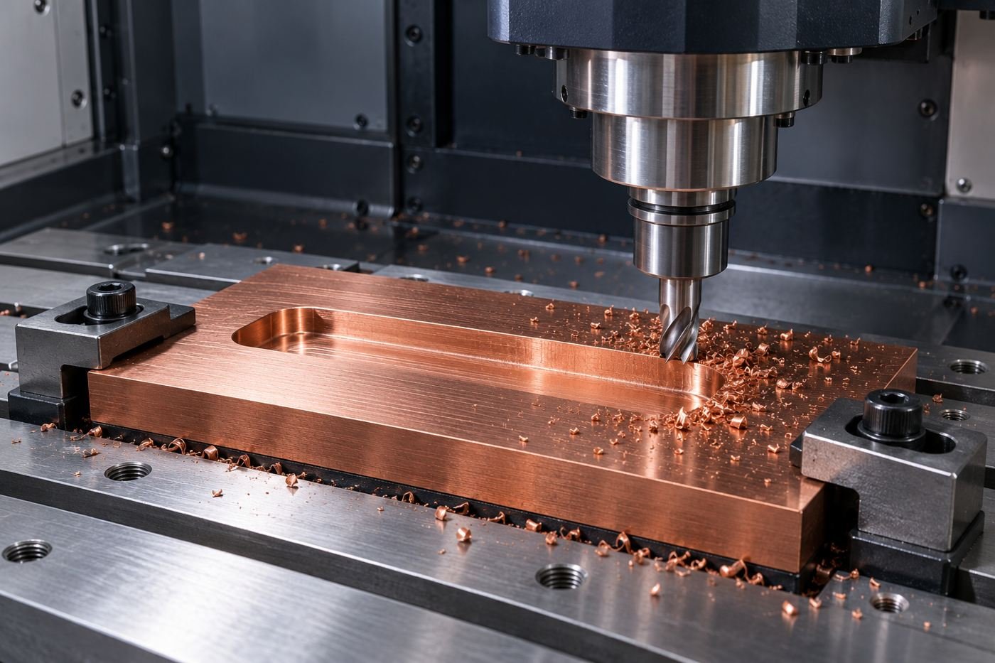
Connect the process to the functional feature
- Milling: open channels, pockets, mounting faces, seal lands and bolt patterns.
- Turning: cylindrical bodies, shoulders, external grooves and concentric mating features.
- Drilling and threading: distribution bores, mounting holes and specified connection ports.
- Secondary operations: discuss deburring, finishing, joining and assembly as defined items in the quotation.
Finishing can change a sealing diameter or the effective width of a groove. Identify masked areas and state whether dimensions apply before or after coating. For joined plates, agree on the final machining and inspection sequence.
MAKE YOUR DRAWING QUOTE-READY
Engineering parameters that need a clear definition
Use the table below to organize an RFQ. Numerical entries are illustrative drawing examples only; they are not standard MileMetal capabilities, recommended design limits or guaranteed acceptance values. The approved drawing and quotation establish the project requirements.
| Parameter | Illustrative specification | Also define |
|---|---|---|
| Critical linear dimension | 25.00 ±0.05 mm | The specific feature, datum relationship and inspection condition; avoid applying tight tolerances to every dimension |
| Contact-face flatness | 0.05 mm over a defined contact area | Area boundary, support or restraint condition, and whether inspection follows joining or coating |
| Surface texture | Ra 1.6 μm on a marked face | Measurement method and direction, functional area, and additional texture limits required by the seal or interface design |
| Channel geometry | Width × depth × internal radius, in mm | Minimum remaining wall, cutter access, corner details, lid position and permitted edge treatment |
| Threaded connection | G 1/4 per the specified thread standard, if selected | Seal arrangement, engagement, gauge requirement and mating-part drawing; parallel threads alone do not define a fluid seal |
| Coating or plating | Thickness and tolerance in μm | Masked surfaces, internal coverage, adhesion criteria and whether sizes are specified before or after treatment |
| Operating and test conditions | Pressure in bar or MPa; temperature in °C; flow in L/min | Fluid, normal operating range, transient conditions, test medium, hold time and acceptance limit |
| Cleanliness | Particle size/count or residue limit under an agreed method | Sampling location, extraction method, drying, inspection evidence and port protection |
A single “precision” figure cannot describe a complete cold plate. Separating size, location, flatness and surface texture makes the requirement easier to manufacture and verify. For sealing grooves, use the selected seal supplier’s geometry and operating assumptions as part of the design input.
DESIGN FOR MANUFACTURING
Resolve costly details before the first part is cut
Deep channels and thin features
A narrow passage may require a long, small-diameter tool. Increasing depth can reduce stiffness and complicate chip evacuation. Share the permitted corner radius and minimum wall thickness so the review can identify access constraints without changing the functional design silently.
Large pockets and flat contact faces
Removing substantial stock can make a part more sensitive to residual stress and clamping. Define the final datum and free-state or restrained inspection condition. A flatness result obtained before lid joining may not describe the completed assembly.
Intersecting passages and trapped debris
Cross-drilled manifolds create internal edges that need a deliberate deburring and cleaning plan. Consider how the intersection will be reached, inspected and flushed. If access plugs are part of the design, include their geometry and sealing requirements.
Prototype changes and repeat orders
Record every approved drawing revision, material substitution and finish change. Reordering against a photograph or an old sample can leave critical requirements ambiguous. Establish the released file set and the characteristics to recheck after a design change.
DEFINE ACCEPTANCE EARLY
A quality plan matched to your drawing
Identify critical characteristics before the order is released. Agree on the inspection method, report format, sampling and traceability needed for your application.
- Geometry: contact-face flatness, groove dimensions, port positions and mating features.
- Surface condition: roughness, edge quality, coatings and damage limits.
- Internal cleanliness: burr removal, particle criteria, cleaning verification and protected ports.
- Documentation: material records, drawing revision and the required inspection evidence.
Leak, proof-pressure, flow and thermal tests answer different questions. If assembled-unit testing is part of the project, define the procedure, equipment capability and acceptance criteria separately.
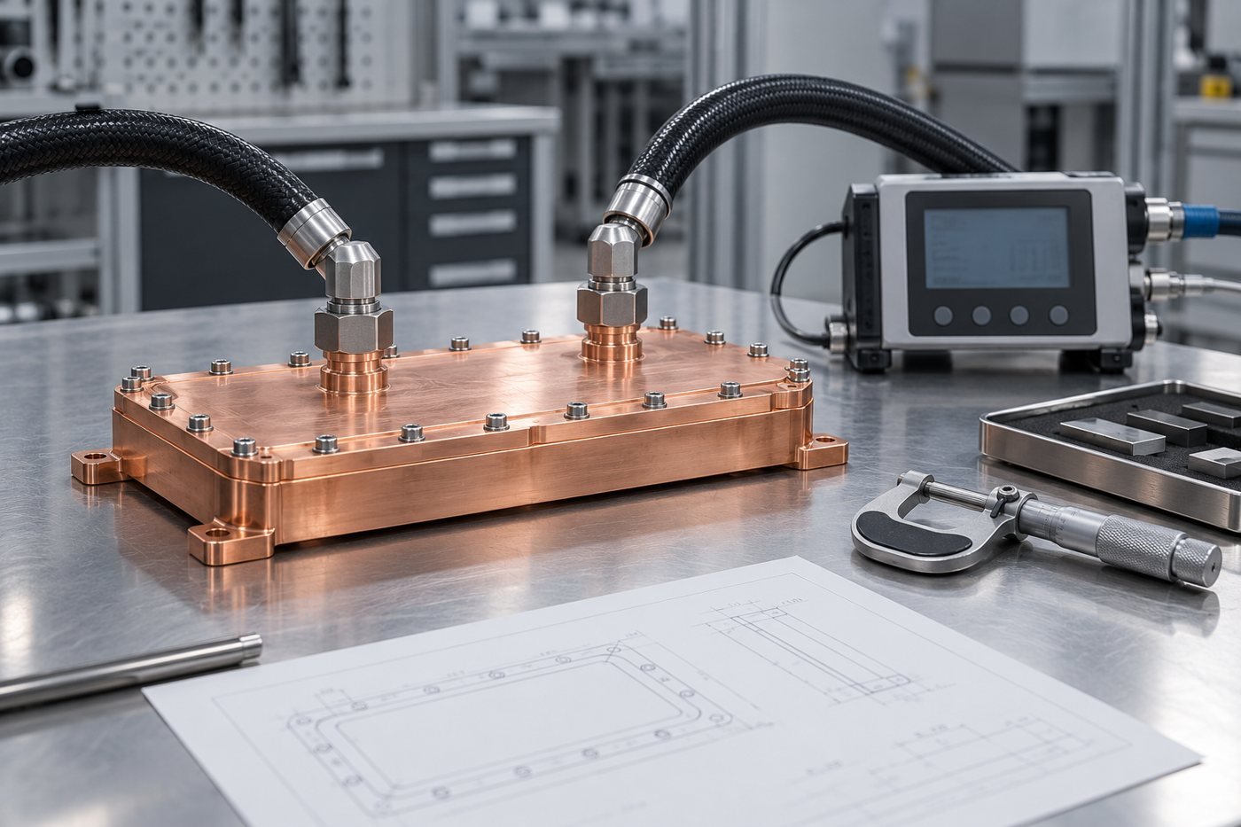
INSPECTION IS NOT ONE SINGLE TEST
Match each quality question to the right evidence
Specify the acceptance plan alongside the drawing. A dimensional report verifies geometry; it does not by itself demonstrate pressure integrity or thermal performance. Request the records needed for the actual scope of supply.
| Quality question | Evidence to agree | Project details needed |
|---|---|---|
| Does the part match the drawing? | Critical-dimension report; appropriate CMM, gauge or surface measurement where specified | Datums, characteristics, sampling and measurement condition |
| Is the specified material used? | Agreed material documentation and lot identification | Grade, condition, document requirements and traceability scope |
| Are flow paths ready for assembly? | Edge-condition and cleanliness verification under the agreed procedure | Accessible inspection areas, particle/residue criteria and protection method |
| Does a completed assembly leak? | Leak-test record if included in the order | Test medium, pressure, stabilization, duration, method and acceptance threshold |
| Can the assembly withstand the specified pressure test? | Proof-test record if included and qualified | Test pressure, duration, safety procedure and post-test criteria |
| Does the cooling design meet its performance target? | Flow/pressure-drop and thermal validation under defined conditions | Coolant, inlet temperature, flow, heat input, interface conditions and system boundaries |
Include any joined or assembled-unit tests explicitly in the RFQ. Availability, execution responsibility and acceptance criteria must be agreed before production. For component-only orders, the customer can incorporate the delivered parts into the final system validation plan.
A CLEAR PATH TO YOUR FIRST ORDER
From drawing package to approved parts
Share the requirements
Send CAD, a controlled drawing, materials, quantity and delivery needs.
Resolve open details
Review tool access, critical features, finishing and inspection scope.
Approve the quotation
Confirm the revision, process scope, acceptance criteria and schedule.
Produce & verify
Manufacture to the agreed requirements and provide the specified records.
START WITH YOUR DRAWING
Planning AI or data center cooling hardware?
Send your component files with the material, quantity and critical requirements. Include coolant and operating conditions when they affect the manufacturing or acceptance plan.
BEFORE YOU SEND YOUR FILES
AI & data center cooling machining FAQs
Can MileMetal review a custom liquid cold plate design?
Yes. Send the base and cover models, controlled drawings, material requirements and intended joining method. Identify the heat-contact area, seal geometry and critical interfaces. The review can then establish machining scope and highlight information needed for a quotation.
Should I choose copper or aluminum for a cold plate?
The choice depends on the thermal design, weight, coolant compatibility, joining method and cost. Compare the complete assembly rather than selecting a material on thermal conductivity alone. Specify the exact alloy and condition, and confirm compatibility with the other wetted materials.
Can internal microchannels be CNC machined?
Feasibility depends on width, depth, radius, aspect ratio, tool access and the stability of the remaining features. Some channel designs require a different manufacturing route. Submit the actual geometry for review rather than relying on a generic minimum feature size.
What tolerances should I put on the drawing?
Start with the assembly’s functional requirements. Identify contact faces, seal features, locating datums and port positions separately, then assign the tolerances each needs. The illustrative parameter table above is a formatting guide; it is not a capability guarantee or a substitute for design analysis.
Does the quotation include lid joining and leak testing?
Only when these operations are explicitly included in the agreed scope. A component machining quotation may cover an open base and separate cover. For a finished assembly, provide the joining specification, test procedure and acceptance criteria so responsibilities can be established.
What files are needed for an accurate quote?
Send a STEP model and a controlled PDF drawing, plus material, finish, quantity and delivery requirements. Include thread standards, seal details and critical inspection notes. Where a model and drawing disagree, identify which governs before releasing the order.
Can I start with prototypes and order more later?
Share the prototype quantity and expected repeat-order demand together. This helps frame tooling, inspection and documentation discussions. Before reordering, confirm the released drawing revision and any changes established during prototype validation.
How should cooling components be packed?
Specify protection for contact faces, seal lands and threads, along with any cleanliness requirements. Agree on drying, individual separation and port caps or covers where needed. Packaging should preserve the verified condition through transport and storage.
Move your cooling component from CAD to a clear production plan
Send your drawings, quantities and critical requirements. MileMetal can review the machining scope and identify the details needed to quote your project.
Request a Component Review →Explore the technical sourcing guide →