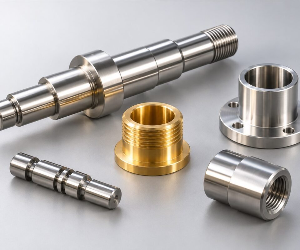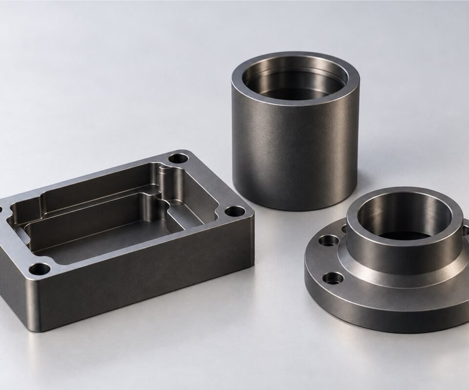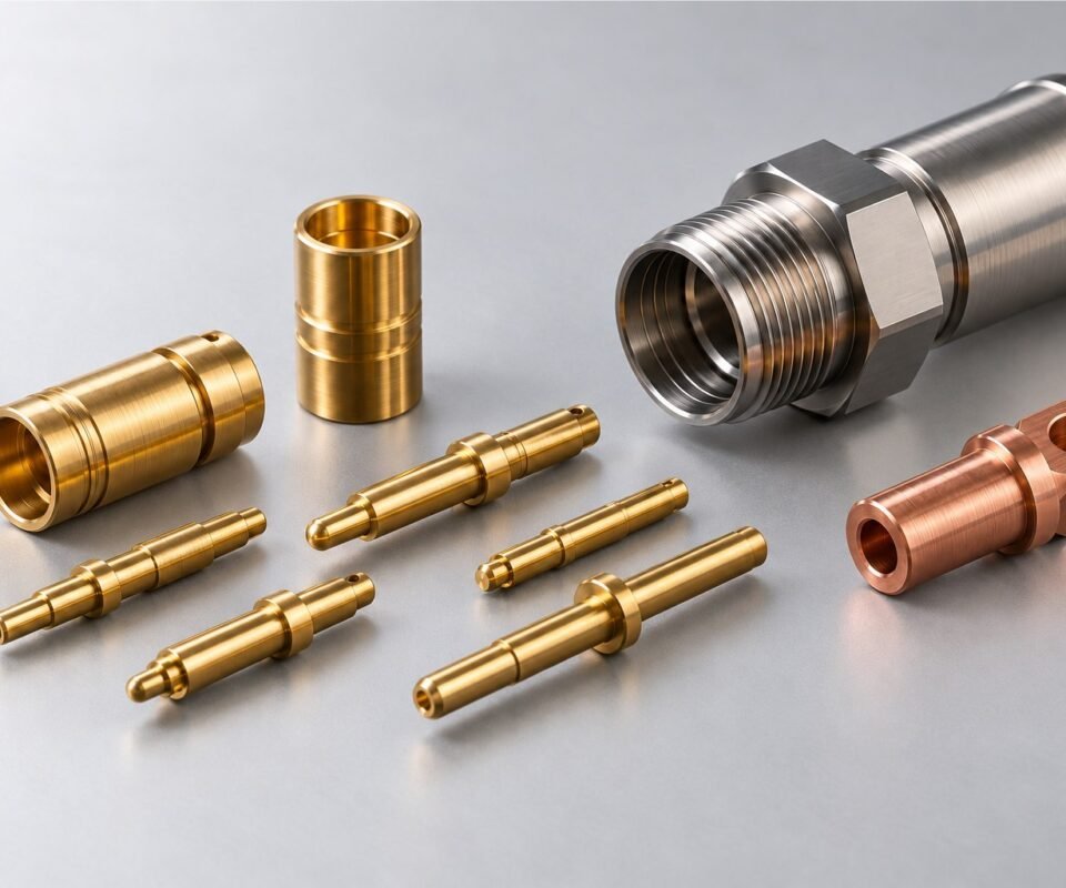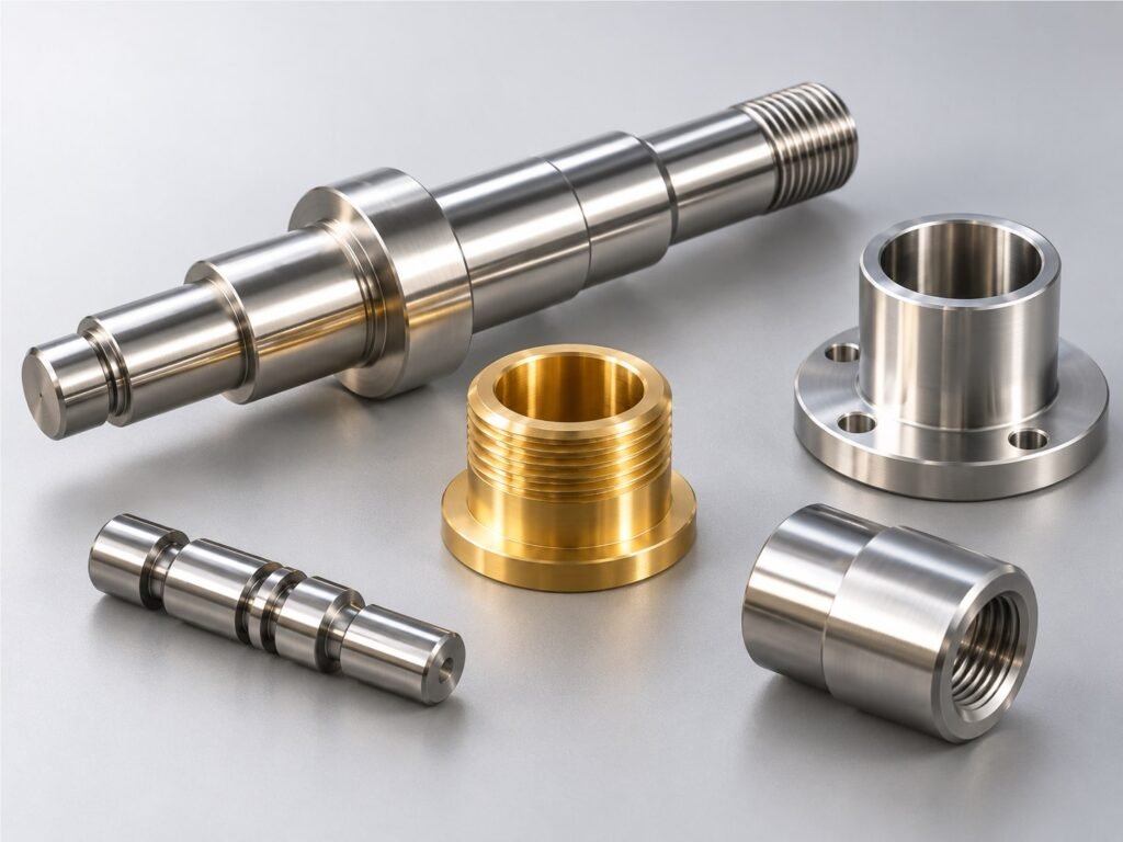

What Is CNC Turning? Process, Materials, Parameters & Design Guide
2026-10-23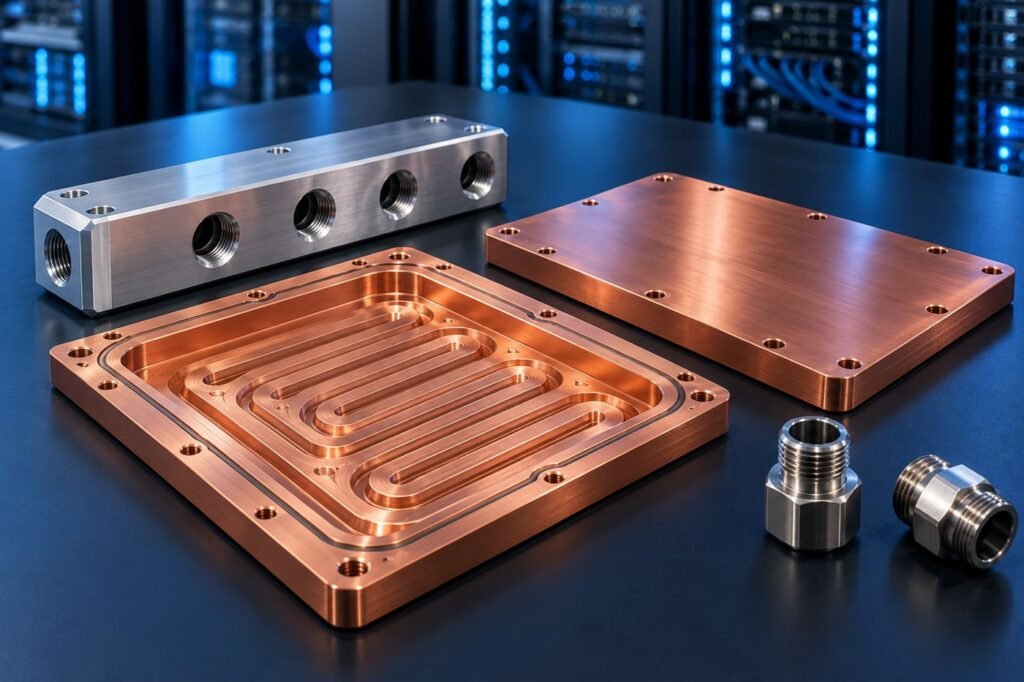
MILEMETAL · PRECISION MACHINING INSIGHTS
CNC Machining for AI Server Liquid Cooling: A Component Design & Sourcing Guide
A cold plate can meet its drawing dimensions and still miss its thermal target. A manifold can pass a leak check and still distribute flow unevenly. Reliable cooling hardware requires geometry, materials, joining, cleanliness and validation to work together.
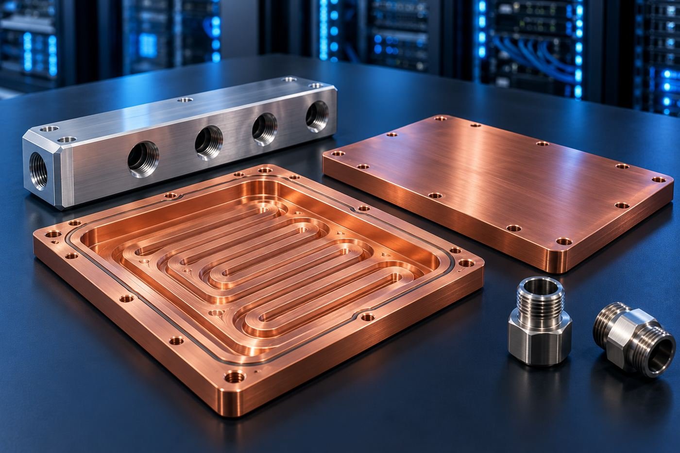
CNC milling and turning produce the contact faces, coolant passages, ports, seal grooves and mounting interfaces used in cold plates, distribution manifolds and fittings. Their value lies in controlling functional geometry. Cooling capacity and leak performance must then be verified on the assembled design under defined operating conditions.
Where machined components fit in a cooling loop
This guide focuses on single-phase, direct-to-chip liquid cooling. Coolant stays liquid while carrying heat away from processor-mounted cold plates. A coolant distribution unit (CDU) interfaces with the cooling circuit; its architecture determines how heat is transferred to the facility system. Immersion and two-phase systems require separate material, sealing and qualification decisions.
| Component | Important features | What the buyer should define |
|---|---|---|
| Cold plate base and lid | Thermal contact face, passages, seal land, mounting pattern | Heat map, interface stack, flow conditions and joining route |
| Supply / return manifold | Header bore, branch ports, closures, mounting faces | Branch demand, pressure-drop budget and service access |
| Adapters and fittings | Threads, sealing faces, bores and wrench flats | Mating interface, seal arrangement and approved materials |
| Quick-disconnect hardware | Valve seats, sliding interfaces, retention and seal features | Qualified coupling interface and assembly-level requirements |
| Mounts and structural parts | Locating features, standoffs and support surfaces | Load path, alignment, allowable movement and electrical constraints |
The component categories above are common to the reference guide from PTSMAKE. The calculations, example specification matrix and procurement workflow below are independently developed for engineering review. They are not claims about a particular server platform or MileMetal production capability.
Start with heat load, coolant flow and pressure drop
A machining drawing should follow a thermal and hydraulic requirement. Before selecting a channel width, establish the heat entering the liquid, coolant inlet temperature, permitted temperature rise, available flow and maximum pressure loss. Specify the fluid formulation and concentration: water and water-glycol mixtures do not have identical properties.
A worked coolant-flow example
For a steady, single-phase energy balance, heat transferred to the coolant is approximately:
Assume Q = 1,000 W, cp = 4,180 J/(kg·K), density ρ = 1,000 kg/m³ and ΔT = 5 K.
ṁ = 1,000 / (4,180 × 5) = 0.0478 kg/s
Volume flow = ṁ / ρ ≈ 2.87 L/min
This is an illustrative water-based calculation with rounded properties. The 1,000 W value is a hypothetical load delivered to the coolant, not a processor specification. It estimates the flow needed for the selected bulk coolant rise; it does not establish chip temperature, local hot-spot temperature or adequate convection inside a particular cold plate.
| Heat transferred to liquid | Mass flow | Volume flow | Interpretation |
|---|---|---|---|
| 500 W | 0.0239 kg/s | 1.44 L/min | Single branch energy balance |
| 1,000 W | 0.0478 kg/s | 2.87 L/min | Worked example above |
| 1,500 W | 0.0718 kg/s | 4.31 L/min | Higher load at unchanged coolant rise |
| 4 × 1,000 W parallel branches | 0.1914 kg/s total | 11.48 L/min total | Assumes each branch receives its required flow |
Keep thermal resistance and pressure loss separate
If an allowed cold-plate contact-surface temperature is 55°C, inlet coolant is 35°C and the imposed heat is 1,000 W, an illustrative surface-to-inlet resistance budget is (55 − 35) / 1,000 = 0.020 K/W. This is not a junction-to-coolant limit. Package resistance, interface material, mounting pressure and measurement locations determine how the full temperature budget is allocated.
Pressure drop must be evaluated at the same flow and fluid conditions. A restriction that improves heat transfer may consume more of the pump budget. Manufacturer data such as Boyd’s CPU/GPU cold plate datasheet illustrates the importance of performance curves; its product values should not be transferred to a different channel design.
For another simple example, 30 kPa pressure loss at 2.87 L/min corresponds to approximately 1.44 W of hydraulic power: Δp × volume flow in m³/s. Electrical pump demand will be higher and depends on efficiency and the rest of the circuit. A parallel loop adds branch flows; it does not add every branch pressure drop as though those branches were in series.
Cold plate machining: connect channel geometry to manufacturing
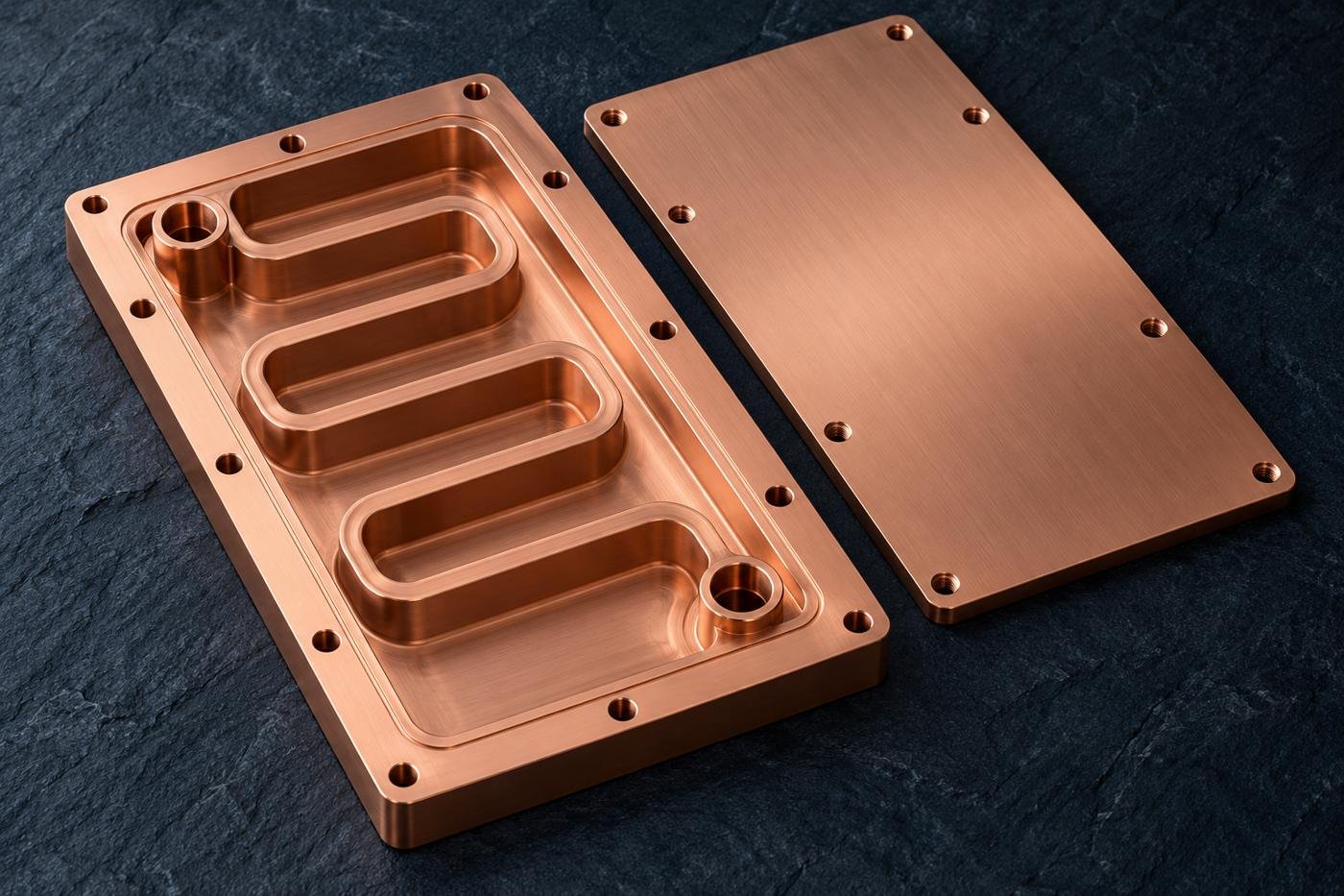
The base must spread heat toward wetted surfaces while supporting the mounting load. The lid must close the flow path without introducing unacceptable deformation. More surface area can be useful, but channel geometry also changes flow distribution, pressure loss, clogging sensitivity and cleaning access.
| Construction | Manufacturing advantage | Design review question |
|---|---|---|
| Milled open channels with a lid | Visible passages before closure; flexible prototype geometry | How will the lid seal or join, and how will distortion be controlled? |
| Drilled passages with closures | Straight tool access and relatively simple machining | Can intersections be deburred and every closure qualified? |
| Fine fins or microchannels | Large wetted area in a compact region | Can the selected process hold the geometry and remove debris reliably? |
| Skived, bonded or brazed structures | Alternative routes for dense internal features | How do joint quality, alloy compatibility and production volume affect selection? |
CNC machining is one part of the manufacturing route. Dense fins may justify skiving or another specialist process, followed by machining of interfaces. Avoid choosing a route from feature size alone: channel depth, fin thickness, aspect ratio, cutter reach and inspection access can change feasibility substantially.
Channel dimensions are functional parameters
Consider a hypothetical rectangular passage 1.00 mm wide and 2.00 mm deep. Its area is 2.00 mm² and its hydraulic diameter, 2wh/(w+h), is approximately 1.33 mm. If width varies by ±0.05 mm while depth stays fixed, the area changes by ±5%. Pressure loss will not necessarily change by the same percentage; it also depends on velocity, hydraulic diameter, length, surface condition and flow regime.
This example explains why an apparently small machining variation may matter to a flow model. It is not a recommended channel size or an achievable-tolerance promise. Validate the actual geometry through analysis and a representative prototype.
Inspect the thermal interface after the important process steps
State the area over which flatness applies, the support condition and whether acceptance is before or after lid joining and finishing. A base that is flat before brazing or welding may move afterward. Mounting torque can introduce further deflection. Thermal-interface-material thickness and loading must be included in the assembly evaluation.
Manifolds, ports and fittings: control the entire flow path
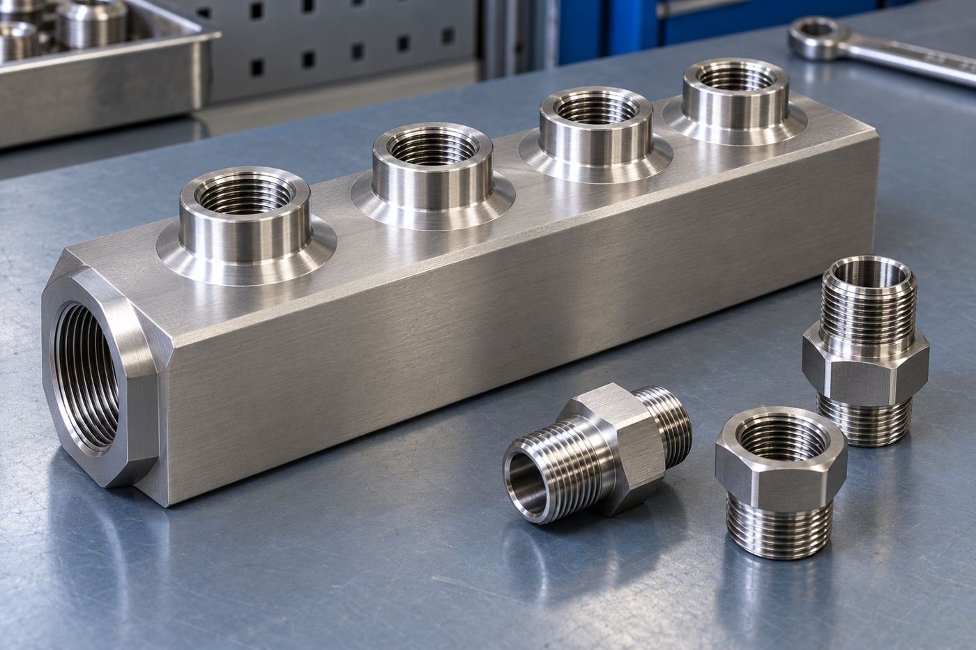
A distribution manifold is more than a row of holes. Header size, branch location, fittings and downstream cold plates all influence branch flow. Supply and return layouts should be considered together. Equal-looking branches are not proof of equal flow, especially when hose lengths and restrictions differ.
Define each port by its complete mating specification. Thread diameter alone does not identify a fluid connection: pitch, thread form, tolerance, sealing method, spotface and engagement length must match. A straight thread may retain a connector while a separate O-ring does the sealing. A tapered thread connection follows a different design and assembly approach.
- Check wrench access. Model the actual fitting envelope and assembly sequence, including neighboring ports.
- Review cross-drill intersections. Identify burr removal and inspection access before closing auxiliary holes.
- Define closures. Treat plugs and joined covers as pressure-boundary features with their own acceptance criteria.
- Allow for service loads. Hose bending and coupling forces should not be carried by a thin wall or an unsupported port.
Quick-disconnect couplings need assembly-level qualification for leakage, flow restriction, connection force and repeated operation. A machined body is not automatically a qualified dry-break coupling. If a standardized or proprietary interface is required, use the approved interface documentation and sourcing arrangement.
For rotational features and thread planning, see MileMetal’s CNC turning process and design guide.
Select materials as a complete wetted system
A high-conductivity base material is useful only if the complete assembly remains compatible with the coolant and operating environment. List every wetted material, including fittings, plating, brazing filler, seals and closure compounds. Assess that list with the coolant supplier and system designer.
| Material / treatment | Potential role | What needs confirmation |
|---|---|---|
| Copper, such as specified C11000 or oxygen-free grades | Heat-spreading base and internal thermal features | Exact grade, condition, joining compatibility and coolant chemistry |
| Aluminum, such as specified 6061 temper | Lightweight bases, manifolds or structural parts | Strength after joining, corrosion control and mixed-metal exposure |
| Stainless steel, such as specified 316L | Manifold bodies, fittings or other compatible fluid hardware | Fluid compatibility, cleanliness and machining requirements |
| Approved brass alloy | Selected adapters and coupling components | Composition, coolant compatibility and any application restrictions |
| Specified nickel coating | Engineered surface barrier on selected parts | Process, thickness, adhesion, porosity and coverage of internal passages |
| Elastomer seal compound | Face seals, port seals and moving coupling seals | Exact compound, hardness, fluid exposure, temperature and compression behavior |
A coating should not be assumed to eliminate mixed-metal corrosion risk. Coverage defects, damaged edges and inaccessible internal surfaces matter. The coolant’s inhibitors, contamination and service history also affect performance. Specify which surfaces are wetted and which are cosmetic before selecting a finish.
Likewise, “EPDM” or “FKM” is a material family, not a complete seal specification. Confirm the particular compound against the coolant formulation, additives and temperature range. An oil-compatible assembly lubricant may be inappropriate for another elastomer or for the coolant cleanliness requirement.
Specify tolerances where they protect thermal contact and sealing
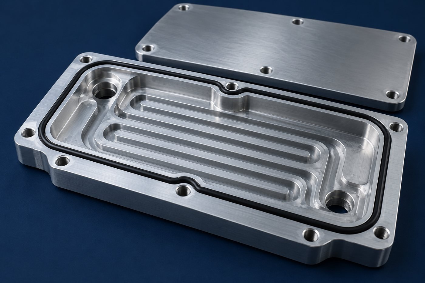
Use separate controls for size, form, location and texture. Flatness is not a bilateral size tolerance. Ra is not a flatness measurement. Port location can be acceptable while a sealing face is scratched, and a smooth face can still be distorted.
| Feature | Example notation or parameter | Acceptance question |
|---|---|---|
| Thermal contact area | 0.05 mm flatness over a defined 80 × 80 mm area | Does this satisfy the interface stack after joining and mounting? |
| Selected sealing contact face | Ra ≤0.8 µm, if selected by the seal designer | Which face, texture direction and evaluation settings apply? |
| Coolant passage width | 1.00 ±0.05 mm in a hypothetical design | What does variation do to local flow and pressure loss? |
| Mounting / port position | Position tolerance relative to identified datums | Can the intended fittings and mount assemble without forced alignment? |
| Seal groove | Depth, width, radii and tolerances from the selected seal design | Are squeeze, available groove volume and extrusion gap acceptable? |
| Coated bore or sealing face | Explicit acceptance before or after coating | Has coating buildup been included in the tolerance stack? |
These are engineering examples, not MileMetal standard capabilities. A tighter number is not automatically a better specification. Use analysis, seal guidance and assembly testing to select values that protect function without unnecessary cost.
The Parker O-Ring Handbook distinguishes sealing contact surfaces from groove surfaces and differentiates operating conditions. Use the applicable installation guidance rather than applying one roughness value to every face.
As a simple geometric illustration, a 2.00 mm seal cross-section compressed to an assembled height of 1.60 mm has nominal squeeze of (2.00 − 1.60) / 2.00 = 20%. This calculation ignores tolerances, stretch, thermal expansion, swelling and available groove volume. It is not a groove-sizing recommendation. The approved seal design must evaluate those effects and the joint’s actual deflection.
Plan machining, joining and cleaning as one route
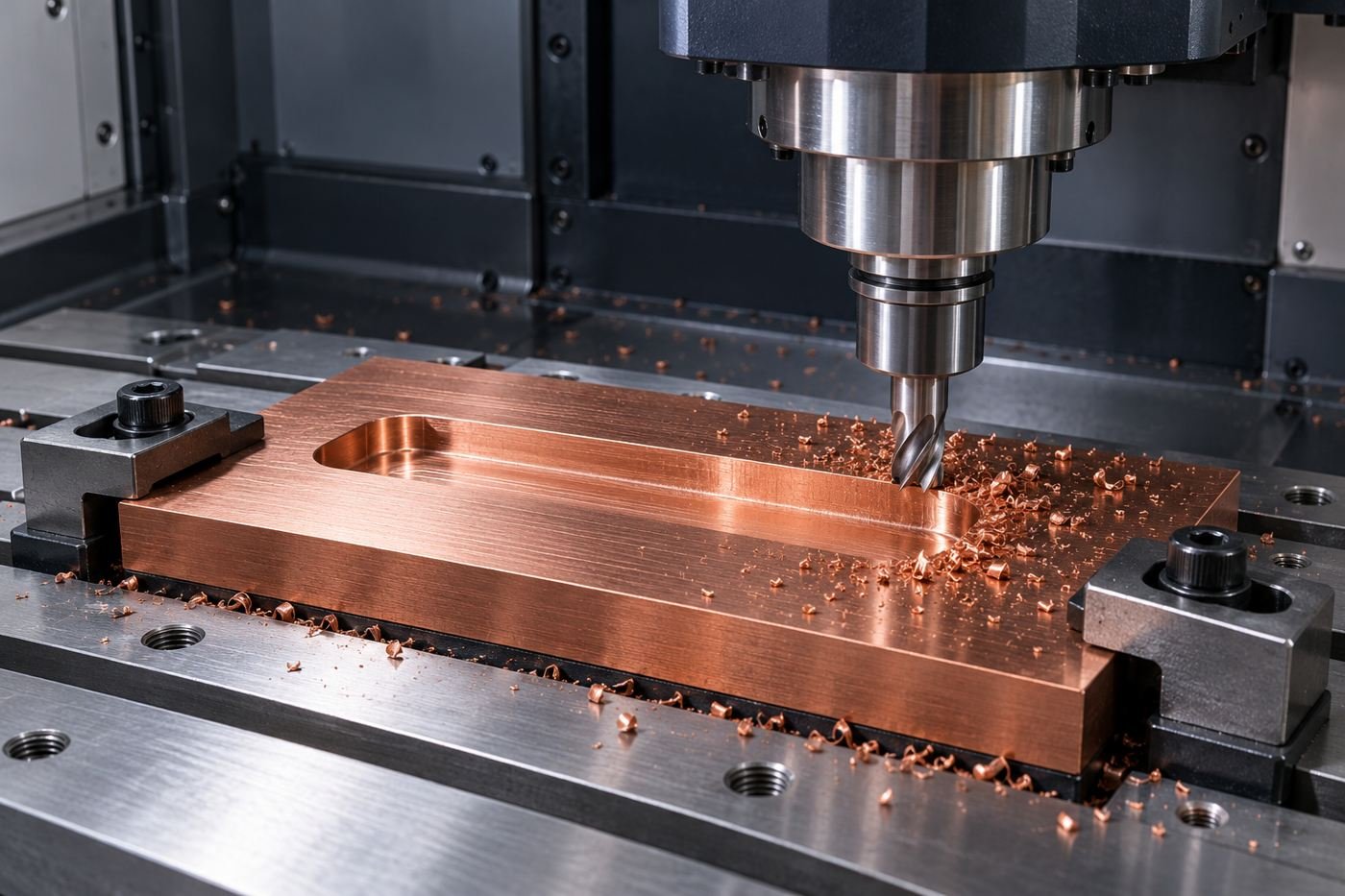
- Review the controlled design. Identify thermal datums, fluid boundaries, critical features and the condition in which each will be inspected.
- Prepare stock and workholding. Plan balanced material removal and support thin sections without obstructing tools.
- Machine open features. Cut channels, ports, grooves and mounting features with tool access and chip removal in mind.
- Deburr and inspect before closure. Check inaccessible intersections and document features that cannot be measured later.
- Join or assemble. Use the qualified lid, plug or seal process, then check for resulting dimensional change.
- Clean and protect. Verify the agreed cleanliness condition, cap ports and prevent shipping contamination.
- Validate the completed boundary. Perform the specified inspection and tests in their agreed order.
For a bolted lid, define fastener type, torque procedure and sequence. For a brazed or welded design, consider the alloy condition after joining and whether final machining is needed. None of these routes removes the need for testing the completed fluid boundary.
“Clean” should have an agreed meaning. Define an extraction or rinse method, particle-size criteria, residue limits where relevant and a reporting format. A final filter cannot be assumed to recover chips trapped inside a narrow passage. Blasting media, polishing compound and cleaning residues need specific controls if they can reach the wetted circuit.
Separate dimensional, leak, pressure and performance validation
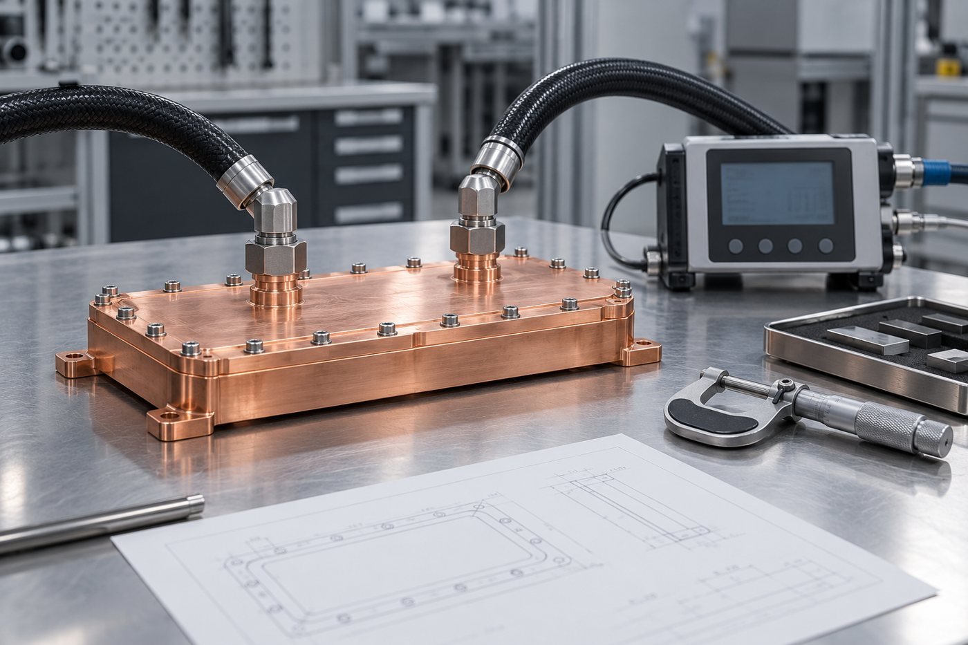
A pass in one category does not establish compliance in the others. The purchaser and manufacturer should agree on the test boundary, medium, conditions, equipment capability and acceptance record before making production hardware.
| Check | What it establishes | Required definition |
|---|---|---|
| Dimensional inspection | Selected drawing features meet their limits | Revision, datums, condition, method and measurement uncertainty |
| Leak test | Leakage is below a defined limit under test conditions | Medium, differential pressure, stabilization, duration, leak-rate units and detection capability |
| Proof / structural pressure test | Response to a specified qualification or acceptance pressure | Approved procedure, pressure boundary, deformation criteria and applicable requirements |
| Flow / pressure-drop test | Hydraulic behavior at specified operating points | Coolant, temperature, flow, pressure-tap locations and allowable range |
| Thermal performance test | Temperature response under an imposed load | Heat map, interface material, mounting load, inlet conditions and sensor locations |
| Durability qualification | Performance after defined exposure or cycling | Thermal / pressure cycles, fluid aging, connector cycles and post-test criteria |
Pressure decay is influenced by trapped volume and temperature stabilization. A gas leak-rate result is not automatically a liquid leak rate in service. Specify the measurement basis and correlate the chosen method with the product requirement. “No visible leak” and “below a quantified leak limit” are different acceptance statements.
Test pressures and durations must come from the approved design, component ratings and applicable requirements. There is no universal pressure multiplier suitable for every server cooling assembly. Production leak screening and design qualification also serve different purposes: agree which checks apply to every unit and which belong to qualification samples.
Maintain traceability between the component serial or lot identifier, material lot, drawing revision, joining process and final test report. This makes a later change in plating, coolant or seal compound easier to evaluate.
Reduce cost with a better RFQ and fewer ambiguous requirements
Cost depends on more than the metal removed. Deep channels, small tools, inaccessible burrs, repeated setups, distortion correction and test fixtures all add effort. A wider tool-access radius or a revised closure detail can matter more than selecting a cheaper stock material.
Prototype orders should answer specific design questions: thermal performance, assembly access, channel manufacturability or seal behavior. Before scaling, confirm that production joining, finishing and inspection represent the qualified build. A prototype made by a different route is useful evidence, but not automatic production validation.
What to send for a machining review
- Controlled files: 3D CAD, 2D drawing, revision, units and identified critical characteristics.
- Operating envelope: heat transferred to coolant, inlet temperature, fluid formulation, flow and pressure-drop budget.
- Materials: alloy, temper, wetted-material list, coating specification and seal compound.
- Interfaces: mating ports, connectors, mounting loads, thermal interface and required keep-out space.
- Assembly route: lid joining or fastening, closures and responsibilities for purchased components.
- Acceptance: inspection, leak-test definition, cleanliness, traceability and qualification requirements.
- Commercial scope: prototype quantity, expected repeat volume, delivery schedule and packaging.
Our CAD file preparation guide can help organize your submission. For fittings and adapters, review the CNC turning service and identify the complete fluid interface in the drawing.
Discuss your liquid-cooling component drawings with MileMetal
Send the component model, material, quantities and functional requirements for a machining feasibility review. Specify whether you need individual parts or an assembled and tested unit so the quotation defines the full scope and any qualification work.
Frequently asked questions
Is copper always better than aluminum for a cold plate?
No single material wins every design. Copper offers strong heat-spreading performance, while mass, joining, geometry, coolant compatibility and total cost also matter. Compare the completed assembly at the required operating point.
Can all microchannels be CNC milled?
No. Feature depth, tool reach, fin stiffness, material behavior and inspection access limit the feasible geometry. Some designs need skiving, etching, bonding or other specialist processes alongside machining.
Does a tight machining tolerance guarantee a leak-free assembly?
No. Sealing also depends on surface damage, joint deformation, seal compound, groove design, joining quality and assembly control. Verify leakage against a defined test requirement.
Can a cold plate be approved from a drawing alone?
A drawing controls geometry and manufacturing requirements. Thermal and hydraulic performance need analysis and representative testing with the defined heat load, coolant and mounting conditions.
What should be included in the leak-test requirement?
State the test medium, pressure differential, stabilization and test duration, maximum allowable leak rate with units, and required detection capability. Identify the completed assembly boundary and record format.