
Allen Bolt Size Chart: Metric & Inch Socket Head Cap Screw Dimensions
2026-11-09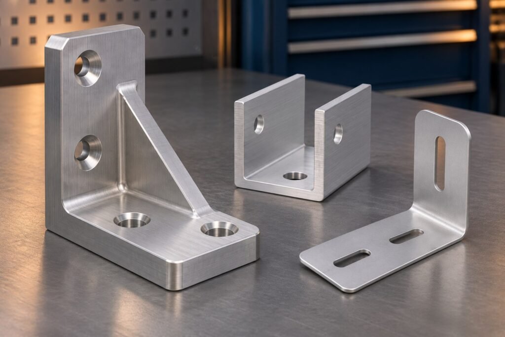
MILEMETAL · COMPONENT DESIGN & MANUFACTURING
Aluminum Mounting Brackets: CNC Machining, Extrusion & Sheet Metal Guide
A mounting bracket can look simple and still decide whether a machine assembles easily, holds alignment and stays quiet in service. Its job is to connect components while controlling their position under load—not merely to provide a few holes.
Aluminum is attractive when weight, corrosion resistance and machining flexibility matter. But the best aluminum bracket is not necessarily machined from a solid block. An extruded section, a bent sheet or a stamped part may achieve the same function with less material and a lower production cost.
In this guide: Process comparison · Alloys and data · CNC machining · Extrusion · Sheet metal and stamping · Design calculations · Finishes · Cost and sourcing
Start with the connection, then choose the bracket
A sensor mount needs to hold position. A motor bracket must also resist torque and vibration. An enclosure support may need little positional precision but still require safe edges, a clean finish and enough clearance for installation tools.
Describe the load direction, mounting points and allowable movement before selecting an alloy or manufacturing method. A longer unsupported arm can bend noticeably even when its stress remains below the material’s yield strength. Adding a return flange or rib may solve that problem more effectively than selecting a higher-strength alloy.
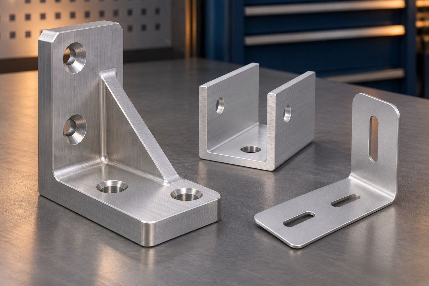
Common shapes include L-brackets, U-brackets, Z-brackets, gusseted mounts, adapter plates and slotted adjustment brackets. Treat these as starting geometries. The final shape should follow the load path and installation sequence, including access to screws after neighboring components are fitted.
Which manufacturing process fits your aluminum bracket?
| Route | Best geometric fit | Upfront commitment | Key limitation | Typical secondary work |
|---|---|---|---|---|
| CNC machining from plate or bar | Pockets, locating bores, ribs, bosses and features on several faces | Programming and workholding | Material removal and machining time can dominate cost | Deburring, inserts and surface finishing |
| Standard extrusion + machining | Angles, channels or other available constant sections | Section sourcing and machining fixtures | Available profile geometry and extrusion variation | Sawing, milling ends, drilling and tapping |
| Custom extrusion + machining | A repeated section with integrated webs or mounting features | Die, trials and minimum production commitment | Features cannot vary freely along the extrusion direction | Cutting to length and precision interface machining |
| Cut sheet + press-brake forming | L, U and Z forms with largely uniform thickness | Programming and suitable bend tooling | Bend access, springback and developed-blank accuracy | Deburring, hardware insertion and finishing |
| Dedicated stamping and forming | Repeatable pierced and formed sheet components | Tool design, manufacture and qualification | Design changes can require tool modification | Tapping, sizing, hardware installation or coating |
There is no universal order quantity at which one method becomes cheaper. The number of bends, machining time, material utilization, tooling complexity and expected design life can move the crossover substantially. Compare complete routes using the same finished-part requirements.
Choose the alloy together with its temper and product form
“Aluminum” is not a complete material specification. The alloy number, temper, product form and applicable purchasing standard all matter. In particular, do not use a typical property for one form as the guaranteed minimum for another.
| Material and condition | Reference mechanical data | Bracket route to consider | Important qualification |
|---|---|---|---|
| 6061-T6 extrusion | Example published minimums: tensile 260 MPa; yield 240 MPa | Machined angles, channels and structural mounting sections | Values refer to a published extrusion specification example; verify the actual section and purchasing standard |
| 6063-T6 extrusion | Industry reference: tensile 205 MPa; yield 170 MPa | Complex profile sections and appearance-sensitive mounts | Reference values are not universal design allowables; thickness and specification affect requirements |
| 5052-H32 rolled sheet | Published sheet range: tensile 215–265 MPa; yield minimum 160 MPa | Bent or stamped sheet brackets | Example source thickness band: over 0.63 through 50 mm; confirm the applicable thickness and material standard |
| 5052-O rolled sheet | Published sheet range: tensile 170–215 MPa; yield minimum 65 MPa | Forming-intensive parts where the final strength is sufficient | Example source thickness band: over 1.2 through 6.3 mm; the softer temper is not an equivalent-strength substitution for H32 |
How to read the table: these figures illustrate the effect of alloy, temper and product form. They combine explicitly identified reference values and specification examples, not a single harmonized acceptance standard. Use the ordered material specification and certificate for production acceptance; evaluate the actual joint separately.
6061 is a useful starting point for machined and extruded components. 6063 is often attractive when a profile’s shape and finish matter. For bent sheet, 5052 offers a different balance of strength and formability. A stronger material can be considered where required, but increasing strength alone does not provide a comparable increase in elastic stiffness.
CNC-machined aluminum brackets: put precision where it matters
Machining from plate or bar gives freedom to combine mounting faces, bores, pockets and integral reinforcement. It is particularly useful when a bracket establishes the relationship between two components: a motor and gearbox, a camera and frame, or a sensor and moving target.
Define datums on the surfaces that locate the assembly. Machine critical hole patterns and locating features relative to those references, and make the inspection plan use the same logic. A tight overall size tolerance will not rescue a hole pattern referenced from the wrong face.
Deep pockets, very thin walls and small internal radii increase machining difficulty. Internal corners normally retain a cutter radius; if a mating square corner must enter the pocket, agree a relief or change the mating geometry. Where extensive stock removal can release residual stress, plan roughing, refixturing and finishing around the required final flatness.
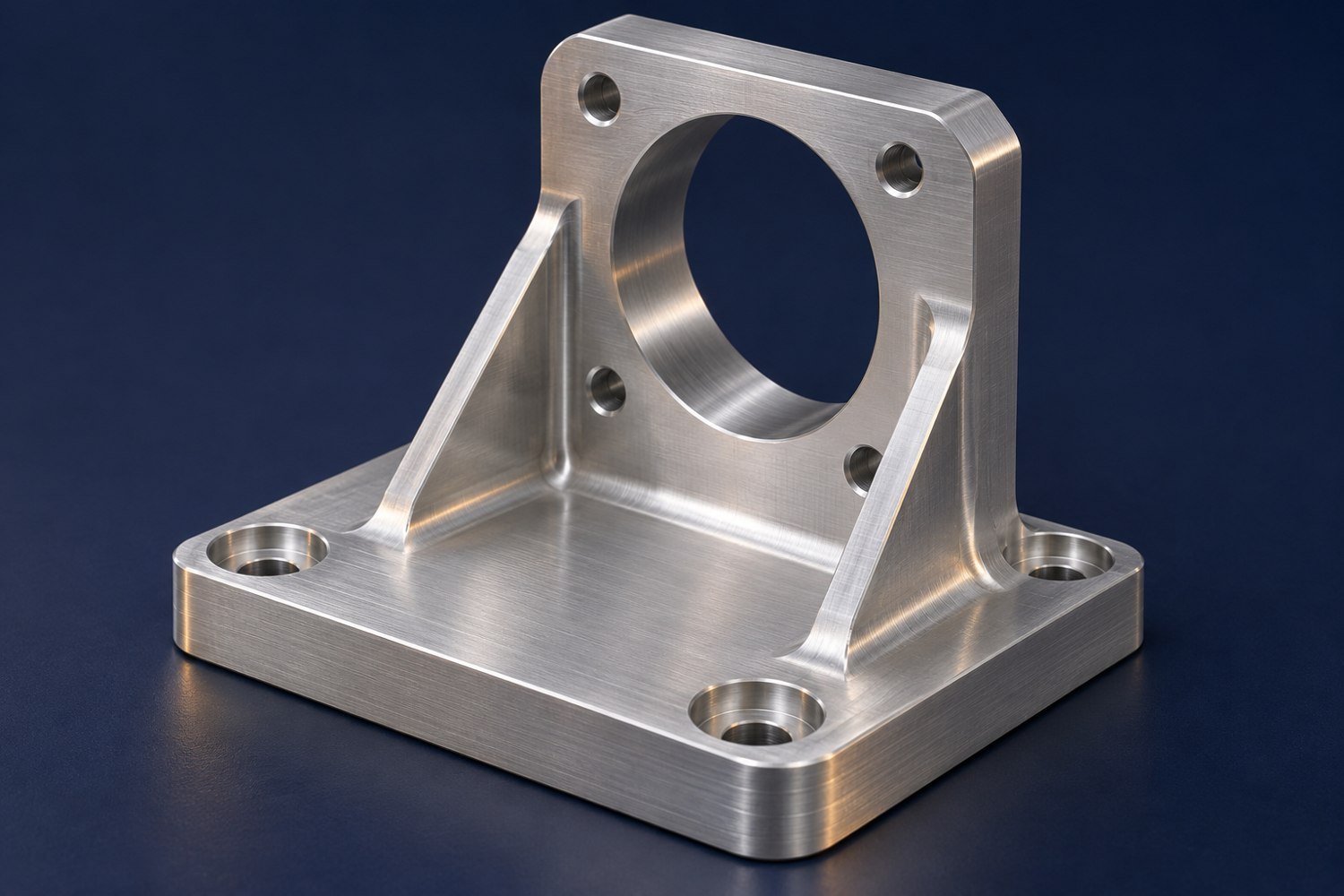
A practical CNC bracket sequence
- Review the material condition, drawing revision and assembly datums.
- Prepare stock and establish reliable locating faces.
- Rough pockets and external geometry while retaining adequate support.
- Finish critical faces, bores and hole patterns in a controlled setup sequence.
- Deburr, install specified hardware and apply the agreed finish.
- Inspect the finished interfaces in their specified delivery condition.
Do not put the tightest possible tolerance on every dimension. Clearance surfaces, appearance edges and locating bores perform different jobs. Separating those requirements lets the manufacturer focus machining and inspection effort where the assembly needs it.
Extruded aluminum brackets: let the section do the work
Extrusion creates a continuous profile with a constant cross-section. Cutting that profile into short lengths can produce a bracket blank close to its final shape, reducing the amount of material removed by machining.
A standard angle or channel is worth evaluating before commissioning a custom die. A custom section becomes more interesting when repeated ribs, webs or mounting lands simplify the part enough to justify tooling and qualification. Extrusion does not eliminate secondary operations: hole patterns, threaded features and precisely located end faces usually still need machining.
Specify which surfaces may remain as extruded and which must be machined. Bow, twist and profile variation matter when a long section is divided into individual parts. If the bracket must sit flat against a machined housing, the mating face may need a finishing cut even when the rest of the profile is acceptable as supplied.
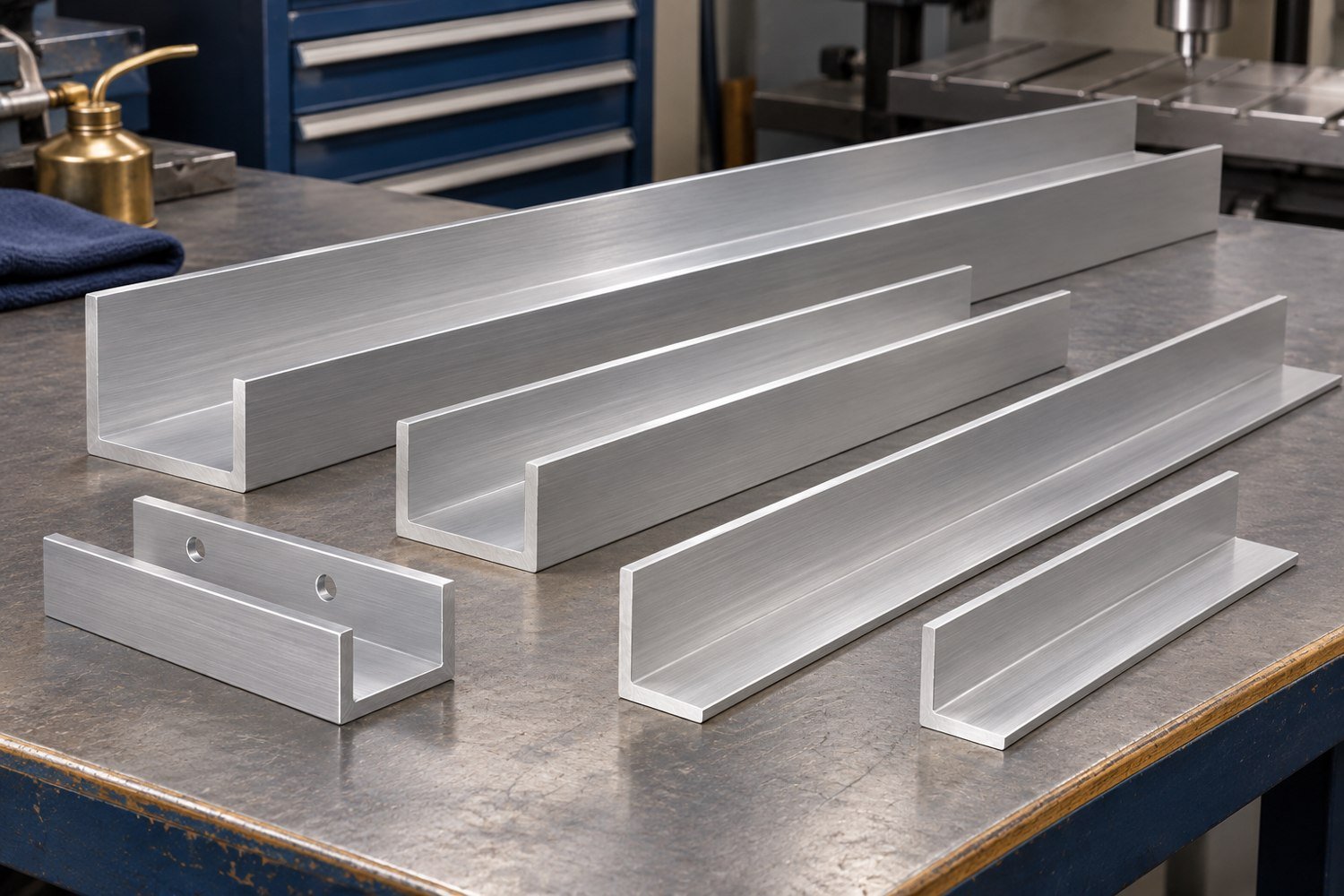
Sheet metal brackets: cutting, bending and stamping
Cut-and-bent sheet for flexible production
For simple thin-wall brackets, a flat blank can be laser cut or punched and then formed on a press brake. This route supports changes to holes, slots and flange lengths without automatically requiring a dedicated stamping die.
Good sheet design starts with the bend. Choose an inside radius suited to the alloy, temper, thickness, grain direction and tooling. Provide bend relief where needed and keep holes out of the deformation zone unless their distortion is intentional and controlled. Features located across two bends inherit more process variation than holes on one flat flange.
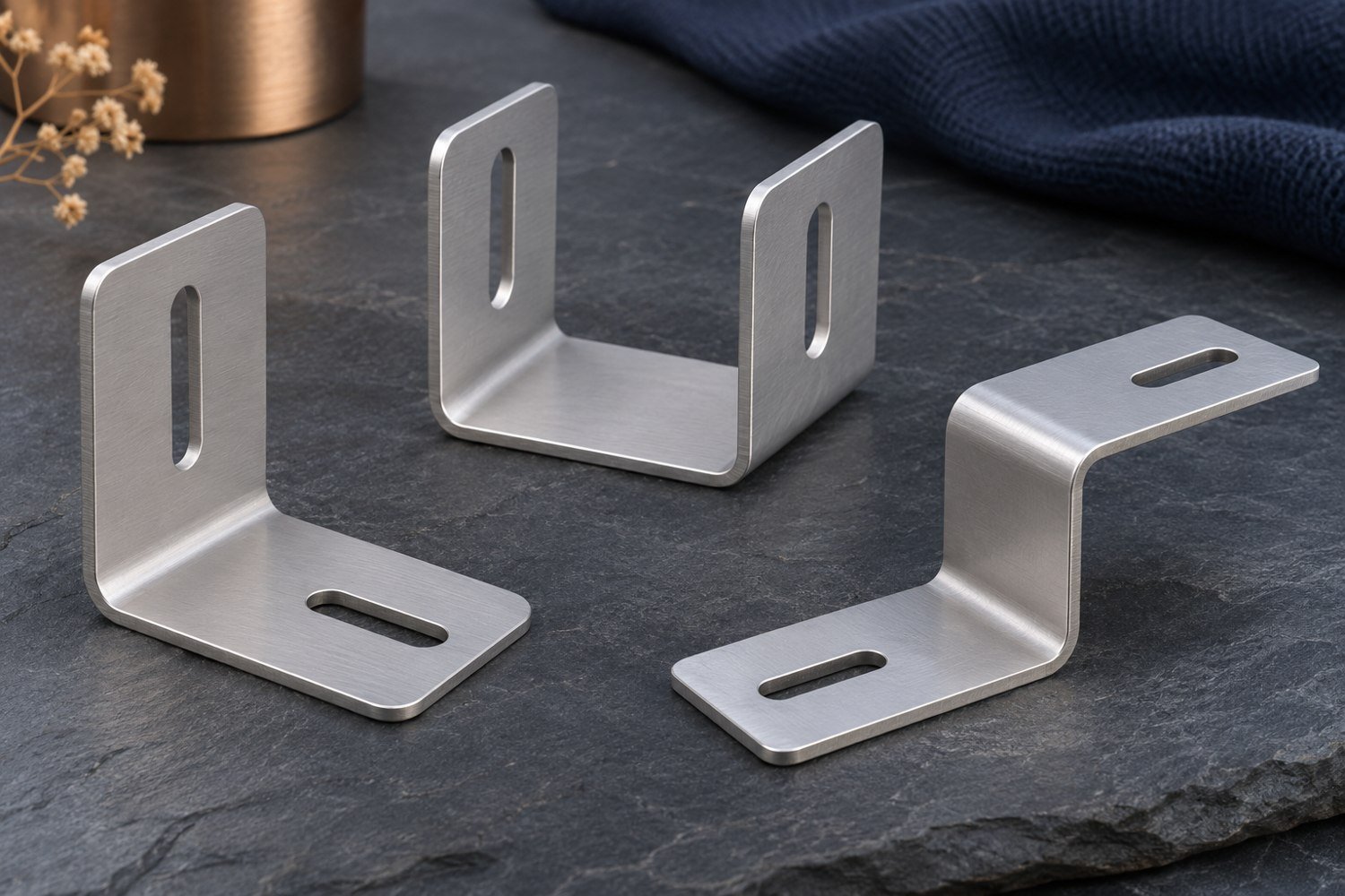
Stamping for a stable repeat design
Stamping can combine blanking, piercing and forming through dedicated tooling. Progressive tooling moves strip through successive stations; other parts may use separate operations. The appropriate tool arrangement depends on the geometry, annual demand, material behavior and handling requirements.
Once the design is stable, tooling can reduce repeated manual handling and improve consistency. The tradeoff is the initial investment and the cost of later changes. Before committing to a production tool, approve the functional design, expected material condition, burr direction and inspection features.
A cut-and-bent prototype can validate fit, but it does not by itself qualify a stamped production process. Final trials should address production-tool springback, edge condition, material feed and repeatability. Holes needed for precise location may require a secondary sizing or machining operation.
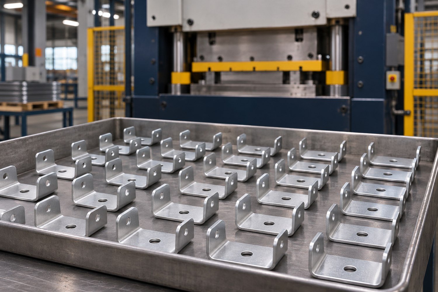
Numerical bend-radius examples for 5052-H32
Published cold-forming guidance for 90° bends provides the following examples. These are starting references for bend trials, not a blanket guarantee for every rolling direction, tool or surface condition.
| Sheet thickness t | Reference inside radius | Radius expressed in mm | What to confirm |
|---|---|---|---|
| 1.6 mm | 1 × t | 1.6 mm | Actual material condition, grain orientation and tool combination |
| 3.2 mm | 1.5 × t | 4.8 mm | Cracking, springback and flange geometry after release |
| 4.8 mm | 1.5 × t | 7.2 mm | Press capability, bend access and final angle |
Useful calculations before requesting a quotation
The following examples show how geometry affects weight, stiffness and fit. All dimensions and loads are illustrative assumptions. They are not a load rating for a finished bracket.
| Design question | Assumed inputs | Calculated result | What it tells you |
|---|---|---|---|
| How much does the flat blank weigh? | 100 × 50 × 3 mm; assumed aluminum density 2.70 g/cm³ | Volume 15 cm³; mass 40.5 g | A baseline before subtracting holes or adding hardware |
| What happens when thickness rises from 3 to 4 mm? | Same rectangular width, span, material and bending direction | Bending stiffness ratio = (4/3)³ = 2.37; mass ratio = 1.33 | Thickness has a cubic effect on simple beam section stiffness |
| How far does a simple strip deflect? | Cantilever: width 30 mm, thickness 4 mm, length 50 mm; end load 20 N; E = 69,000 N/mm² | I = 160 mm⁴; tip deflection ≈ 0.0755 mm | Illustrates elastic beam behavior; ignores bolt compliance and local effects |
| What is the nominal bending stress in that strip? | Same assumed cantilever | σ = 6FL/(bt²) = 12.5 MPa | Not a design approval: holes, fatigue and stress concentrations remain to be checked |
| How much clearance does an M6 screw have in a 6.6 mm hole? | Nominal screw diameter 6.0 mm; example hole diameter 6.6 mm | 0.6 mm diametral or 0.3 mm radial clearance | Illustrates fit only; tolerance, position and actual fastener dimensions still matter |
For the cantilever example, the relationships are I = bt³/12 and δ = FL³/(3EI). Doubling the unsupported length would increase the predicted deflection eightfold if the other assumptions stayed the same. This is why moving a mounting point closer to the load can be more effective than changing the alloy.
Real brackets also experience bolt slip, prying, contact deformation and vibration. Include those effects in the appropriate analysis or physical validation. A gusset changes the load path, so its benefit cannot be represented simply by substituting a higher material strength into the strip calculation.
Hole patterns, slots and tolerances that support assembly
Use slots where adjustment is required and positive locating features where the position must repeat. A slot can make installation easier, but it also allows movement unless the joint is designed to hold the load. For precise repositioning, consider a locating bore, dowel arrangement or defined mating surface.
| Feature | Requirement to define | Manufacturing or inspection implication |
|---|---|---|
| Mounting face | Flatness and relationship to assembly datums | May require machining after forming or extrusion |
| Hole pattern | Hole size and position relative to the functional datums | Measure as a pattern, not just individual edge distances |
| Adjustment slot | Travel, width, end radius and washer bearing area | Check fastener clearance and retained material around the slot |
| Threaded feature | Thread designation, usable depth and finish condition | Confirm engagement, gauge access and blind-hole clearance |
| Bent flange | Final angle, reference condition and inspection restraint | Allow for springback and measurement consistency |
| Visible surface | Permitted marks, texture, color and protected areas | Agree an appearance sample when consistency matters |
There is no single tolerance that describes “CNC quality” or “stamped quality.” A machined bore and a free-state bent flange require different controls. Put functional requirements on the drawing, then confirm a feasible manufacturing and inspection plan.
Finishing and corrosion protection
The finish must work with the assembly. Anodizing can change fitted dimensions, and coating on a contact face can affect seating. Identify threaded holes, locating bores, bearing faces and electrical contact points before the finish is applied.
| Finish route | Reason to consider it | Drawing or quotation detail |
|---|---|---|
| As-machined or mill finish | Simple internal components with agreed surface requirements | Edge breaks, permissible marks and cleanliness |
| Decorative/protective anodizing | Appearance and corrosion protection | Color, coating specification, sealing, masked areas and final dimensions |
| Hardcoat anodizing | Selected wear-contact surfaces | Thickness, dimensional allowance and whether the application needs this coating |
| Conversion coating | Paint preparation or specified contact requirements | Exact chemistry/performance specification and electrical requirements where applicable |
| Powder coating | Colored exposed brackets and equipment hardware | Coating thickness, masking, adhesion requirements and contact-face protection |
Where aluminum contacts dissimilar metals in a wet environment, assess galvanic corrosion as part of the joint design. Isolation, drainage and finish selection may be necessary. The fastener material alone does not resolve every corrosion problem.
Inspection should follow the finished part’s function
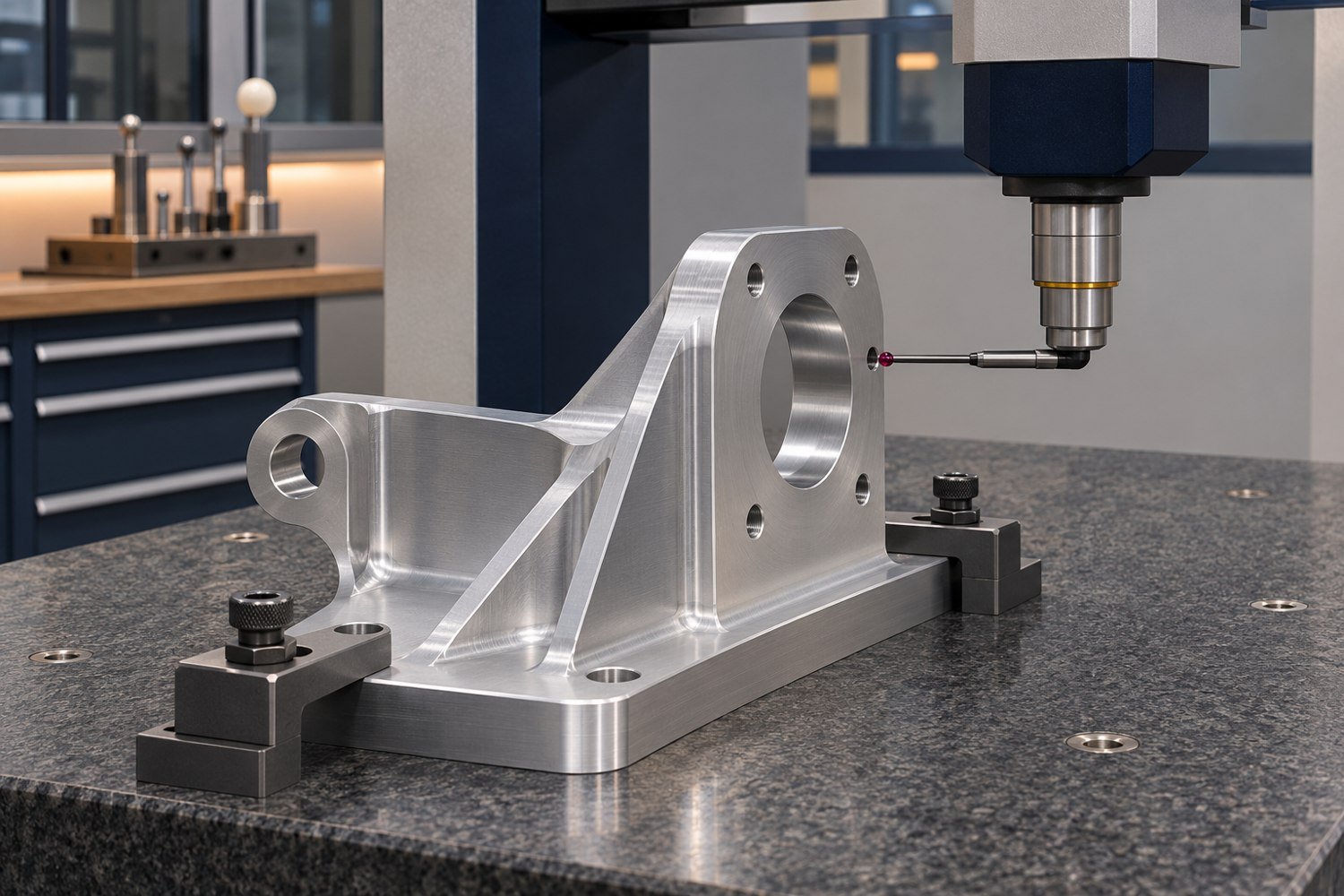
For a machined mount, verify locating bores, mating faces and the critical hole pattern. For a bent bracket, include flange angle and the final relationship between holes on different faces. For an extrusion-based part, check the relevant profile variation as well as the features added by machining.
Agree whether dimensions apply before or after finishing, and whether a flexible part is measured restrained or free. A part can appear acceptable in a fixture yet move after release. Record the approved revision and acceptance method so repeat batches are evaluated consistently.
Compare total cost, not only the cutting cycle
A useful quotation separates tooling from repeat unit cost. It also identifies material, finishing, inspection and any secondary work. When these items are mixed together differently across quotations, the lowest apparent piece price may not represent the lowest delivered cost.
For a simple comparison, assume two fully defined routes produce the same accepted part. Route A has an illustrative setup cost of $300 and a variable cost of $12 per part. Route B has $6,000 in tooling and a variable cost of $3 per part. These numbers demonstrate the calculation only; they are not MileMetal prices.
| Quantity | Route A: $300 + $12N | Route B: $6,000 + $3N | Lower illustrative total |
|---|---|---|---|
| 100 parts | $1,500 | $6,300 | Route A |
| 500 parts | $6,300 | $7,500 | Route A |
| 1,000 parts | $12,300 | $9,000 | Route B |
The theoretical crossover is (6,000 − 300) ÷ (12 − 3) ≈ 634 parts, rounded up to a whole part. Actual decisions must also include tooling maintenance, scrap, changes, inventory and cash tied up in production. A design likely to change next month may not justify a die even when a simple calculation favors it.
What to send for a custom aluminum bracket quotation
- A 3D model and dimensioned drawing with a clear revision identifier.
- Alloy, temper, product form and any permitted material alternatives.
- Assembly datums, critical tolerances and mating-fastener details.
- Load information or the already-approved design requirements.
- Prototype quantity, production batch size and expected repeat demand.
- Finish specification, masked surfaces and appearance requirements.
- Inspection, material documentation, packaging and delivery requirements.
For sheet parts, include the formed model rather than only a flat outline. For extruded parts, distinguish the proposed section from the finished machined geometry. For CNC parts, identify which dimensions establish fit so those features receive the appropriate review.
Frequently asked questions
Is CNC machining always best for aluminum mounting brackets?
No. CNC machining is useful for complex interfaces and precise features. A standard extrusion or a bent sheet may be more economical when it satisfies the same load, alignment and finish requirements.
Which alloy is better: 6061, 6063 or 5052?
The process and service requirements decide. 6061 is widely considered for machined and structural sections, 6063 for extruded profiles, and 5052 for formed sheet. Specify temper and product form before comparing mechanical data.
Can an extruded bracket also be CNC machined?
Yes. Extrusion can supply the basic section while CNC operations create end faces, bores, slots and threaded features. This combination can reduce stock removal while retaining precision where needed.
When should a bent bracket move to stamping?
Evaluate stamping when the design is stable and repeat demand can recover tooling and qualification costs. Compare the full route, including any secondary operations and likely design changes.
How thick should an aluminum bracket be?
Thickness depends on load, span, geometry, fastening and allowable movement. The numerical examples in this guide illustrate trends; they do not specify a safe thickness for an individual application.
Does anodizing affect mounting holes?
It can affect fitted dimensions and surface condition. Define final hole requirements, masking and coating allowance before production rather than assuming the finish has no dimensional effect.
What is the most important drawing information?
The functional datums, critical interfaces, material condition and finish requirements. These tell the manufacturer how the bracket must work in the assembly and how acceptance will be measured.
Review your aluminum bracket manufacturing route
Send MileMetal your drawing, quantities and assembly requirements. We can review the enquiry around CNC machining, extrusion-based blanks or sheet metal processing and confirm the proposed supply scope before quotation.
Related guides: OEM manufacturing enquiries · Socket head screw dimensions · Hardcoat anodizing design