
MILEMETAL · MARINE
CNC Machining for Marine Equipment Components
Marine equipment needs parts that fit, can be assembled reliably and remain practical to service. MileMetal reviews drawings for custom housings, flanges, shafts, bushings and mounting hardware used in marine equipment projects.
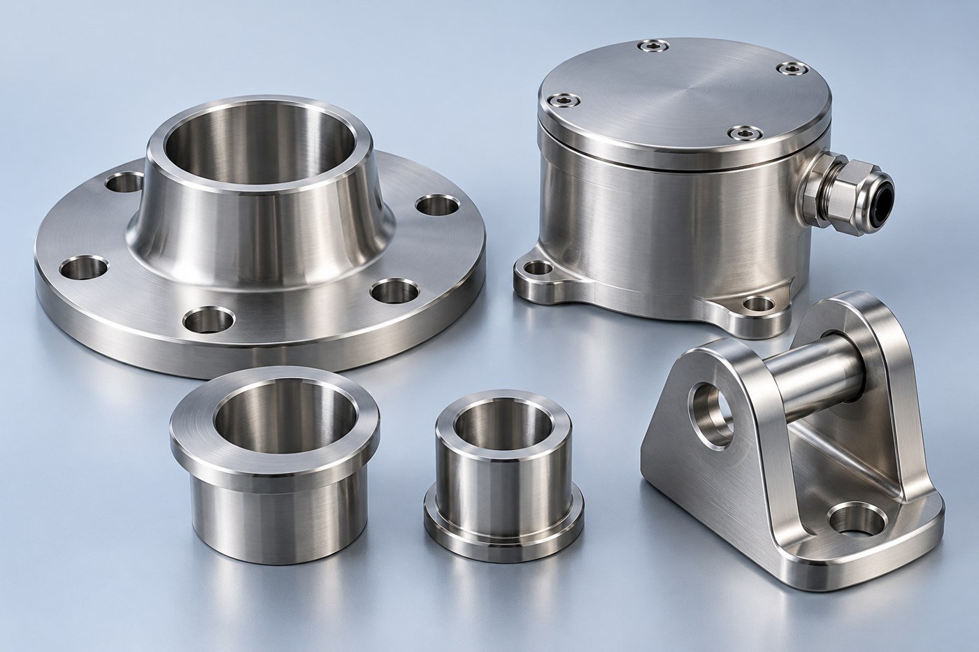
Describe the exposure before choosing the manufacturing details
“Marine” does not describe one operating condition. A component inside an instrument enclosure, a bracket exposed to spray and a part in continuous contact with water need different design decisions. Include the actual exposure, neighboring materials and maintenance arrangement in the enquiry.
The machining review can then focus on the geometry your design depends on: a shaft seat, a flange face, a cover joint or an accessible fastening point. For replacements, separate the original design intent from the condition of the worn part. Photographs are useful context, but a controlled drawing gives production and inspection a shared reference.
Build the enclosure around its connections and service points
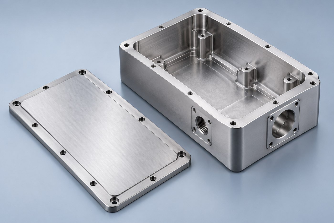
An instrument housing has to accommodate more than its contents. Cable entries, connectors, covers and installation tools all need space. Include these surrounding items in an assembly view, especially where a housing sits close to a bulkhead or another piece of equipment.
Where a cover uses a gasket or seal, define the relevant joint geometry and the surface requirements of the mating faces. Keep cosmetic surfaces separate from functional sealing areas. If a finish is specified, state whether the dimensions apply before or after that operation.
A machined enclosure does not establish a completed product’s ingress rating on its own. Connectors, seals, fasteners and assembly practice are part of that result. Give the component drawing the requirements it needs, then verify the assembled equipment against its intended acceptance criteria.
FROM THE MILEMETAL MEDIA LIBRARY
Part forms and the work behind them
These existing product and workshop photographs show relevant geometries and manufacturing activities. They are separate examples, rather than a single customer project.
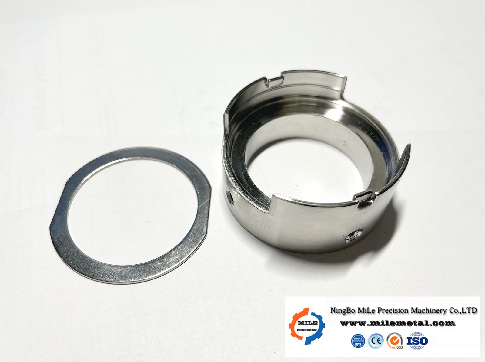
Ring and sleeve components
Circular components showing thin sections, grooves and turned interfaces.

Machined circular plates
Circular plates with central and peripheral openings.

Cylindrical housing example
A cylindrical metal part with an internal bore and side openings.

Flange geometry
A circular flange with a repeated mounting pattern.

Stepped drive component
A metal drive component with stepped round and square features.

Housing with machined faces
A housing example with a central bore and front mounting face.
Where these components fit
Marine instruments
Housings, connector supports and faceplates bring electronics into a serviceable mechanical package. Include the installation space and sealing interfaces.
Mechanical equipment
Shafts, sleeves, flanges and bearing-related components depend on controlled fits. State the operating context and any required material or inspection records.
Mounting and service hardware
Brackets, spacers and replaceable pins need practical access as well as defined dimensions. An assembly view can reveal constraints that a standalone part model misses.
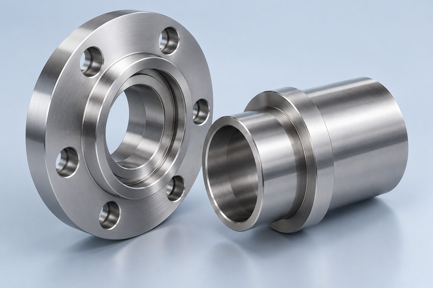
Flanges, shafts and sleeves need a common reference
A circular part can contain several unrelated-looking dimensions that must work together. A bore may locate a shaft while a flange face sets its axial position. Define the datum scheme around those functional relationships so measurement reflects the way the assembly is used.
For a mating fit, provide the required limits and the acceptance condition. If heat treatment or coating is included, the finished size should be unambiguous. Show reliefs, edge breaks and seal-contact areas where they matter to assembly and service.
If a connection carries pressure or has a regulated role, identify the governing requirements in the enquiry. Machining to a drawing, conducting a specified test and approving an assembly for service are distinct responsibilities that need a clear scope.
Choosing the material and finish
Choose a grade for the service conditions rather than relying on a generic “marine-grade” label. Include exposure, mating materials, finish and maintenance needs so your material requirements can be reviewed accurately. Substitutions should be agreed before production.
| Material to discuss | Typical component enquiry | Details to include |
|---|---|---|
| Stainless steel, specified grade | Housings, shafts and connection hardware | Identify actual exposure, surface treatment and material documentation. |
| Aluminum, specified alloy | Instrument housings and selected supports | Define coating, neighboring materials and finished fits. |
| Bronze or brass, specified alloy | Bushings, adapters and selected hardware | Specify the exact alloy and suitability requirements for the service. |
| Engineering polymer, specified grade | Guides, spacers and selected wear parts | Include water exposure, temperature, loading and dimensional conditions. |
Material availability and process scope are confirmed against your drawing and quotation. Include any restrictions on substitutions or approved sources.
The drawing details worth resolving early
Use the component’s function to decide what needs close control. The following details give the machining and inspection review a useful starting point.
| Feature | What to define | Why it helps |
|---|---|---|
| Cover joint | Seal geometry, mating face and fastener pattern | Connects the component requirements to the assembled enclosure. |
| Shaft or sleeve fit | Size limits, datum relationship and final condition | Makes installation and inspection consistent. |
| Flange face | Reference surface, hole pattern and connection details | Defines how the two assemblies meet. |
| Service feature | Extraction direction and tool clearance | Helps the part remain accessible after installation. |
| Surface treatment | Specified process and protected areas | Separates finish requirements from critical mating surfaces. |
Leave room for maintenance
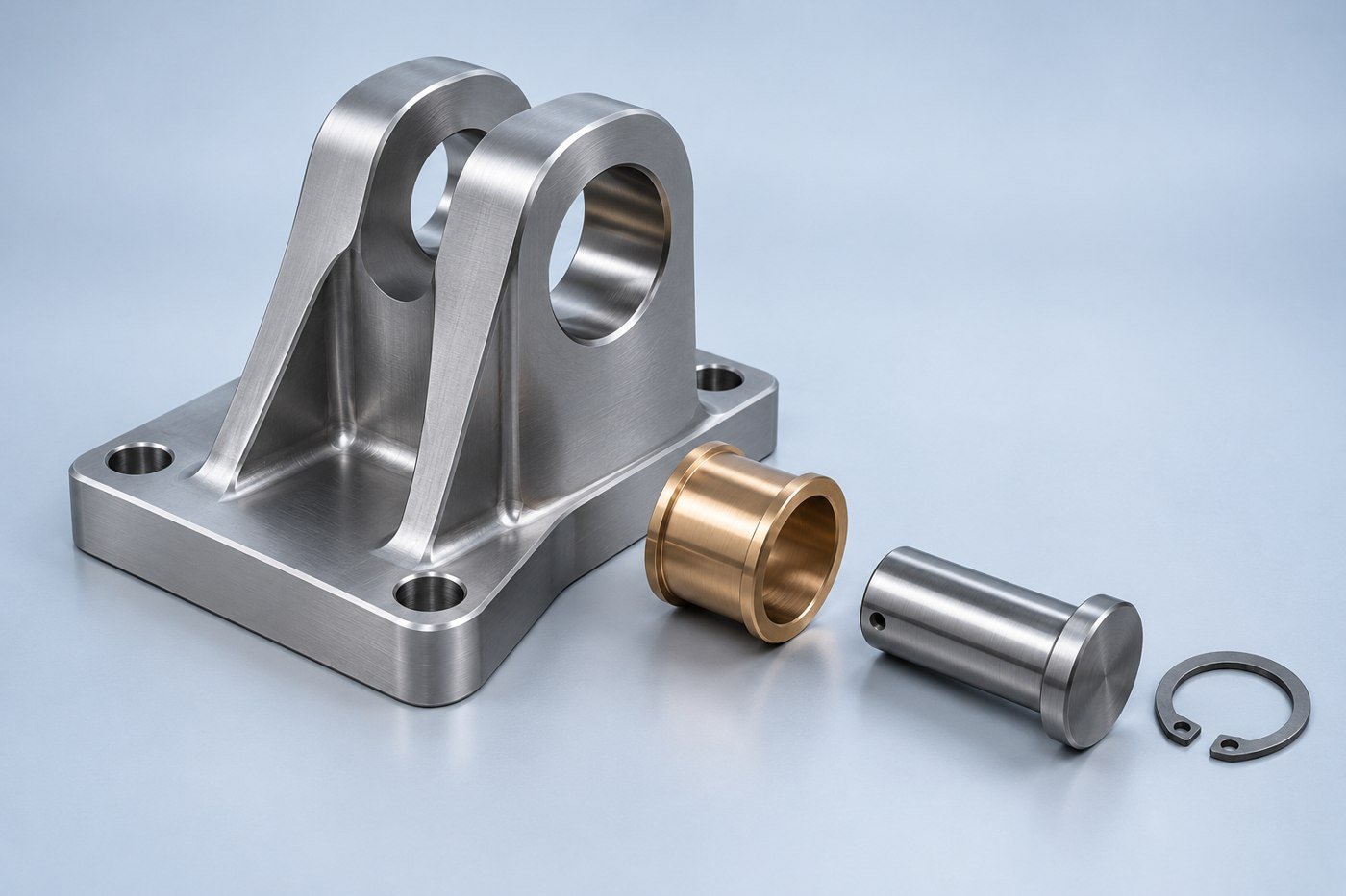
A bracket that is easy to install on a bench may be awkward to remove in an equipment space. Check the direction in which a pin is withdrawn and the space required for a spanner or driver. The surrounding assembly can determine whether a simple part is practical in service.
Where a bushing, wear sleeve or pin is intended to be replaced, identify the replaceable element and the surfaces that locate it. Keep the service part number and revision clear. That makes later orders easier to match to the equipment actually installed.
For visible or handled components, describe the edge condition and finish expectations. Packaging also matters: keep mating surfaces and cosmetic faces protected from contact with other parts during transport.
Inspection that follows the function of the part
For marine equipment parts, begin inspection planning with the mating geometry. A useful report identifies the relevant drawing revision and shows the dimensions that determine fit, rather than presenting unrelated measurements without context.
Confirm any material traceability, surface treatment records or agreed testing in the order. The selection of material for the environment and the qualification of the completed equipment remain part of the project’s engineering requirements.
Put numbers where they help the drawing
Clear callouts are easier to quote and inspect than a general request for “high precision.” The examples below show the format of a requirement, not recommended design values or a guarantee of machining capability.
| Characteristic | Illustrative format | Complete the definition |
|---|---|---|
| Critical size | 25.00 ±0.05 mm | Identify the feature and the condition in which it is accepted. |
| Surface texture | Ra 1.6 μm on a marked face | Define the area and any measurement requirements. |
| Flatness | 0.05 mm over a designated face | State the support condition and whether acceptance follows finishing. |
| Thread | Full designation, class and usable depth | Include blind-hole clearance and the required finished condition. |
Where the design depends on a purchased bearing, connector, motor or other mating part, include that interface information. It is usually more useful than tightening unrelated dimensions across the entire component.
A straightforward way to start
Send a STEP model and a dimensioned drawing with the material, finish, quantity and delivery needs. Add an assembly view when it explains a fit or an access constraint. We can then review the component and identify the open details needed for a quotation.
Before production, agree on the released revision, any secondary operations and the inspection records to be supplied. After a first build, keep approved changes in the same controlled file set. This gives the next order a clear starting point instead of a trail of disconnected notes.
Questions before your first order
Is stainless steel always suitable for marine use?
The grade must be selected for the actual service, including exposure and neighboring materials. Supply the approved grade and finish rather than relying on the word stainless alone.
Can you work from a worn replacement part?
A sample can support the review, but wear may obscure the intended dimensions. Provide drawings or establish an approved drawing before production.
Can you machine a sealed instrument housing?
Send the housing and cover geometry, seal details, connector interfaces and finish requirements. Any assembled ingress test needs a separately defined scope.
What should I include for a shaft?
Provide bearing and seal interfaces, critical dimensions, datums, material condition and any heat treatment or finishing requirements.
Can I specify material documentation?
Yes. State the required document type and traceability needs at quotation so the supply and records can be reviewed together.
How should I define a coated fit?
Identify whether the stated limits apply to the finished coated component and mark surfaces that require masking or further processing.
START A CONVERSATION
Let’s discuss your marine components
Share your drawing package and tell us which parts you need first. Include the features that matter to the assembly so the quotation can address the work you actually need.