
MILEMETAL · AUTOMATION
CNC Machining for Automation Equipment
Build the mechanical details that keep an automation cell working together. MileMetal machines custom fixture parts, gripper components, mounting plates and locating hardware from your drawings.
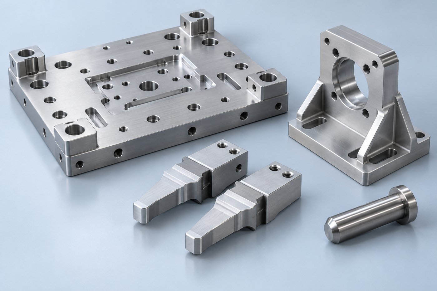
Automation depends on the small interfaces between machines
A production cell brings several systems together: a gripper picks up a part, a fixture locates it, a sensor confirms its position and another operation begins. The interfaces between those steps are often custom machined parts. Their shape may be simple, but the way they locate and release the workpiece deserves careful attention.
We welcome enquiries from equipment builders and automation teams developing these interfaces. Share the workpiece envelope, mating components and installation constraints so the machining review reflects the way the cell will actually be assembled and maintained.
Design the fingers around the workpiece, not just the gripper body
The connection to the gripper is only one side of a finger design. The other side has to contact the workpiece without obstructing the next operation. Include the workpiece geometry and the range of parts the tooling is expected to handle.
Mark the actual contact surfaces. If pads or inserts are replaceable, define how they locate and how they can be changed. A small replaceable contact element can be easier to revise than an entire machined finger, provided the interface is designed clearly.
The application designer establishes gripping forces, motion and safe operating conditions. The component drawing should translate those decisions into dimensions, material and surface requirements that can be manufactured and checked.
FROM THE MILEMETAL MEDIA LIBRARY
Part forms and the work behind them
These existing product and workshop photographs show relevant geometries and manufacturing activities. They are separate examples, rather than a single customer project.

Equipment mounting bracket
A machined bracket with several mounting and access features.

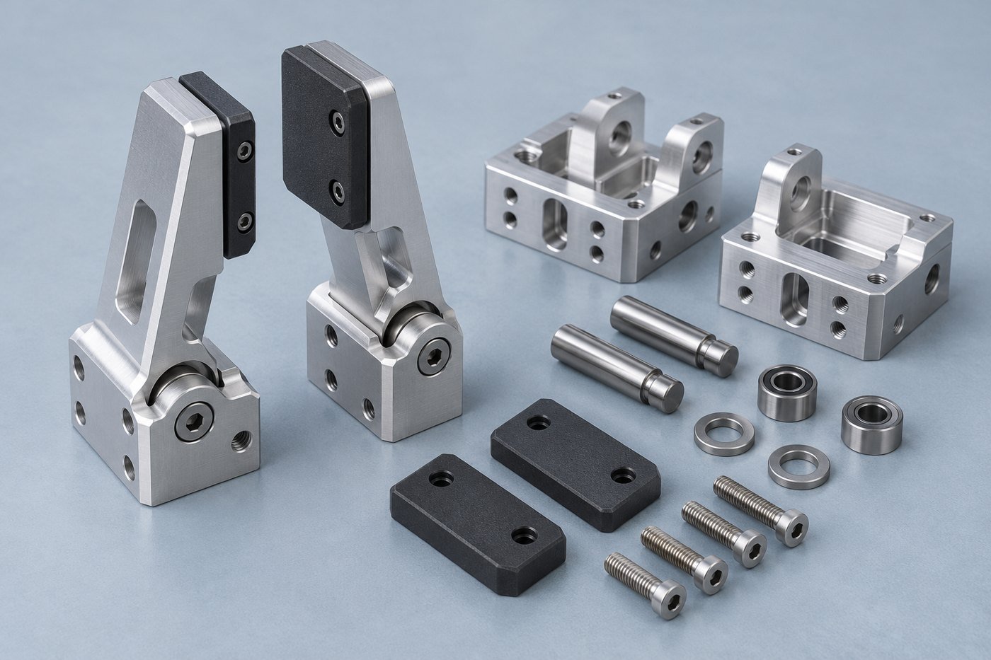
Mechanical support structure
A pocketed aluminum structure with multiple assembly interfaces.

Locating and shaft forms
A group of stepped shafts illustrating cylindrical component geometry.
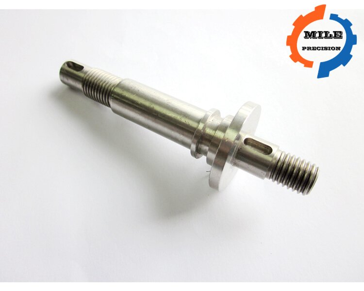
Threaded shaft component
A shaft example combining threads, shoulders and a locating diameter.
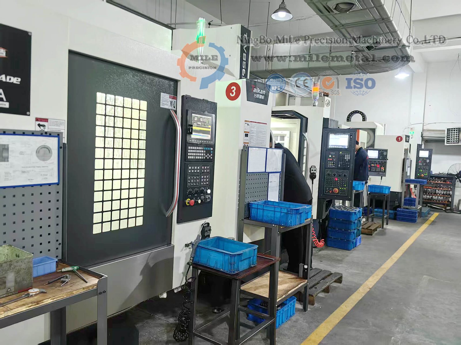
CNC machining equipment
Workshop machinery from the MileMetal media library.

Dimensional measurement
CMM inspection examples from the MileMetal media library.
Mechanical components throughout the cell
Handling and gripping
Custom fingers, adapters and workpiece supports connect a standard actuator or robot to a specific product.
Assembly and inspection fixtures
Nests, plates, locating pins and stops establish the position needed for the next operation or measurement.
Motion and sensing modules
Motor mounts, guide supports and sensor brackets tie purchased components into a coordinated machine layout.
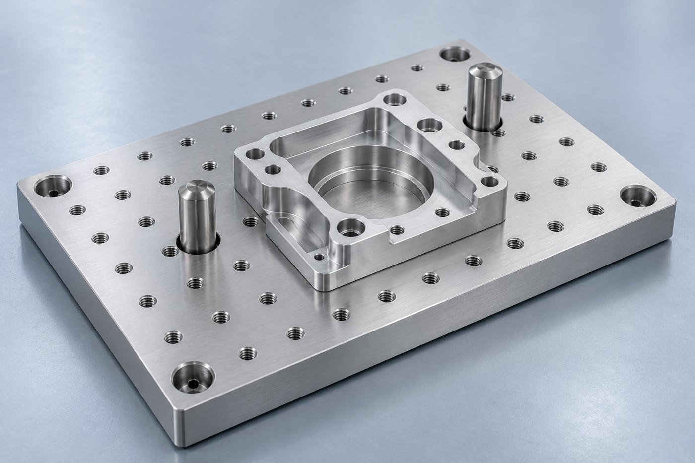
A repeatable fixture begins with an unambiguous locating scheme
A hole grid is useful, but it does not explain how the workpiece should sit. Identify the surfaces and pins that locate it, the clamps that hold it and the direction in which it will be loaded. That makes the fixture easier to build, inspect and use.
Think through the whole cycle. The robot or operator needs room to load and release the part, chips or debris need somewhere to go, and maintenance tools need access to replaceable elements. An assembly model helps reveal conflicts that are easy to miss on a single-part drawing.
For families of products, describe which nest or pin changes between variants. Clear identification and a controlled revision prevent similar-looking fixture elements from being mixed during a changeover.
Choosing the material and finish
Different parts in the same cell can need different materials. A support plate may prioritize mass, a locating pin may prioritize its finished fit, and a contact pad may need to protect the workpiece. Specify the grade and condition for each item rather than assigning one material to the whole assembly.
| Material to discuss | Typical component enquiry | Details to include |
|---|---|---|
| Aluminum 6061 | Fixture plates, brackets and lightweight supports | Define wall thickness, mounting datums and finish. |
| Steel, specified grade | Locating pins, shafts and wear-related elements | Include hardness, heat treatment and any grinding requirements. |
| Stainless steel | Specified hardware and supports | Describe cleaning or environmental exposure and surface requirements. |
| POM, PEEK or specified polymer | Contact pads, guides and insulating parts | Identify the workpiece contact, load, temperature and replacement needs. |
Material availability and process scope are confirmed against your drawing and quotation. Include any restrictions on substitutions or approved sources.
The drawing details worth resolving early
Use the component’s function to decide what needs close control. The following details give the machining and inspection review a useful starting point.
| Feature | What to define | Why it helps |
|---|---|---|
| Fixture datums | Locating faces, pins and clamping arrangement | Makes the intended setup clear to both manufacturing and assembly. |
| Gripper contact | Workpiece geometry and contact surface limits | Connects the part drawing to the handling task. |
| Motor or rail seat | Mating interface and geometric relationships | Establishes the alignment requirements. |
| Replaceable element | Fit, retention and identification | Supports maintenance and changeover. |
| Sensor bracket | Mounting envelope and adjustment range | Allows installation and setting without interference. |
Keep alignment and service access in the same conversation
Motor mounts and guide plates often connect purchased motion components to a custom machine frame. Include the supplier interface drawings for the motor, rail or bearing block so the mounting requirements do not have to be reconstructed from photographs.
Define the seating surfaces and locating features separately from clearance holes. If the assembly uses adjustment, show the intended range and how the position will be locked. This gives machining and inspection a direct connection to the installation method.
Leave room for the next person to work on the machine. A part that can only be removed after several unrelated modules are dismantled may need an access change before the design is released.
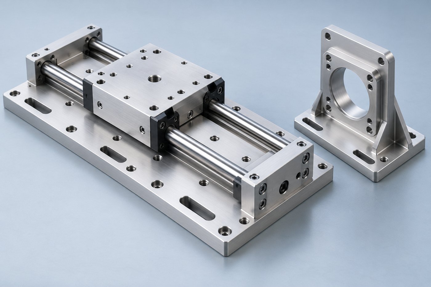
Verify the setup your machine will rely on
For a fixture, the important check may be the relationship between a locating pin and a reference face. For a motor mount, it may be the seat and hole pattern. Highlight those features so the inspection plan follows the function of the part.
After a trial build, incorporate approved changes into the released files. Record which fixture elements belong to each product version and specify the inspection records needed on repeat orders. Component verification supports the build; the complete automation cell still needs its own commissioning and safety assessment.
Put numbers where they help the drawing
Clear callouts are easier to quote and inspect than a general request for “high precision.” The examples below show the format of a requirement, not recommended design values or a guarantee of machining capability.
| Characteristic | Illustrative format | Complete the definition |
|---|---|---|
| Critical size | 25.00 ±0.05 mm | Identify the feature and the condition in which it is accepted. |
| Surface texture | Ra 1.6 μm on a marked face | Define the area and any measurement requirements. |
| Flatness | 0.05 mm over a designated face | State the support condition and whether acceptance follows finishing. |
| Thread | Full designation, class and usable depth | Include blind-hole clearance and the required finished condition. |
Where the design depends on a purchased bearing, connector, motor or other mating part, include that interface information. It is usually more useful than tightening unrelated dimensions across the entire component.
A straightforward way to start
Send a STEP model and a dimensioned drawing with the material, finish, quantity and delivery needs. Add an assembly view when it explains a fit or an access constraint. We can then review the component and identify the open details needed for a quotation.
Before production, agree on the released revision, any secondary operations and the inspection records to be supplied. After a first build, keep approved changes in the same controlled file set. This gives the next order a clear starting point instead of a trail of disconnected notes.
Questions before your first order
Can you machine custom gripper fingers?
Send the finger drawing, gripper interface and workpiece geometry. Mark contact areas and include the material, finish and quantity.
What helps when quoting a fixture?
Provide the fixture parts and an assembly view showing locating points, clamps and loading access. Explain which elements are replaceable or adjustable.
Can I order one set before a larger machine build?
Include the trial quantity and expected repeat demand. Explain what the first set needs to establish so the manufacturing scope matches the evaluation.
How should wear components be specified?
State the material, hardness or treatment, finished fit and replacement criteria. Confirm which dimensions are accepted after all processing.
Do you supply complete automation cells?
This page covers custom machined mechanical components. Any assembly or additional scope needs to be stated and agreed in the quotation.
How do I keep fixture revisions under control?
Use part numbers and revisions for the base and replaceable elements. Record which workpiece revision each setup supports, and release approved changes together.
START A CONVERSATION
Let’s review the custom parts in your automation cell
Share your drawing package and tell us which parts you need first. Include the features that matter to the assembly so the quotation can address the work you actually need.