
MILEMETAL · ELECTRONICS
CNC Machining for Electronics Components
Give your electronics a housing that fits the board, the connectors and the way the product will be assembled. MileMetal machines custom enclosures, mounting parts and mechanical interfaces from your drawings.
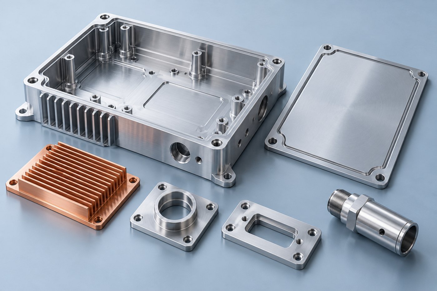
The mechanical details that bring an electronic product together
A board can be ready for testing while the enclosure still needs work. A connector opening is slightly misplaced, a screw cannot be reached, or a cover presses against a cable. These are small mechanical details, but they can delay an otherwise promising build. Bringing the board outline and mating hardware into the machining review helps catch them before the first housing is made.
We welcome enquiries for instrument housings, electronics chassis, sensor bodies, faceplates and related components. Start with the parts you have already defined. If the mechanical layout is still developing, explain what the next prototype needs to prove so the quotation reflects that stage of the project.
Start with the board—and leave room for the person assembling it
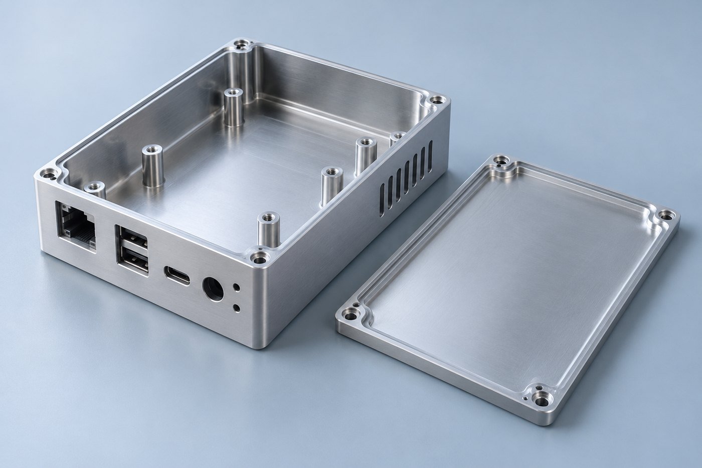
The board outline is only the beginning of an enclosure design. Connector bodies extend beyond it, cables need space to turn, and tools need access to the fasteners. A model of the surrounding assembly is often more useful than another decimal place on an outside dimension.
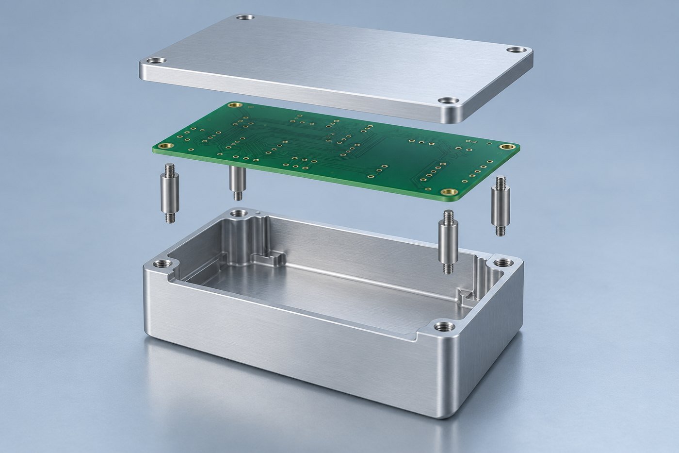
Pay particular attention to standoff heights, cover clearance and the order of assembly. A removable lid should be removable after the connectors are installed. Where a connector locates against a wall, show the mating interface and the clearance needed to insert it. These details help turn a good-looking enclosure into a practical product.
For visible housings, mark the cosmetic faces and describe the expected finish. Keep those requirements separate from board seats, gasket lands and other functional surfaces, which may need a different treatment.
FROM THE MILEMETAL MEDIA LIBRARY
Part forms and the work behind them
These existing product and workshop photographs show relevant geometries and manufacturing activities. They are separate examples, rather than a single customer project.

Compact machined enclosure
A circular opening and mounting pattern within a compact housing.

Housing with side access
An example of a machined housing with openings on several faces.

Instrument panel
A machined metal panel with multiple connector and control openings.

Shaped aluminum housing
A shaped housing example showing pockets and curved exterior geometry.
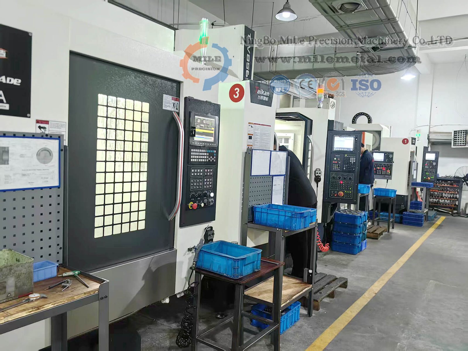
CNC machining workshop
Machining equipment from the MileMetal media library.

Dimensional inspection
CMM inspection examples from the MileMetal media library.
Parts around the electronics
Instrumentation
Faceplates, sensor housings and internal mounting parts bring the electrical and mechanical layouts together. Include control and display envelopes when they affect access or appearance.
Embedded and industrial electronics
Enclosures and chassis may need connector clearance, mounting strength and service access in a confined space. Define the installation arrangement as well as the standalone part.
Power and thermal assemblies
Heat spreaders, support plates and housings can connect thermal and mechanical functions. Identify the contact faces and how the finished assembly will be tested.
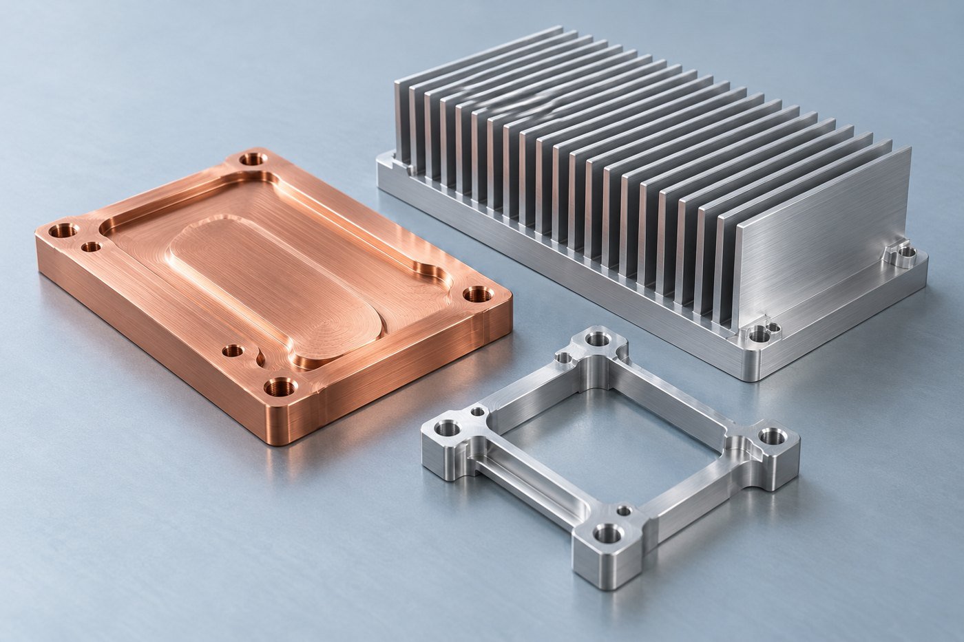
Treat the thermal path as a set of real contact surfaces
A heat spreader, mounting plate or finned housing can become part of the product’s thermal design. The machining discussion should focus on the surfaces that touch: where the component sits, how it is clamped and what interface material lies between the parts.
Specify the relevant face geometry and surface condition rather than asking for every surface to be equally smooth. If a coating is used, identify areas that must remain uncoated for contact or assembly. The same approach applies to electrical bonding surfaces and connector interfaces.
Machining produces the specified geometry. The assembled product still needs to be evaluated under its intended heat load, airflow and installation conditions. Share those constraints where they influence the component design.
Choosing the material and finish
Aluminum is a useful starting point for many housings, but the right choice depends on what the part must do. A thermal interface, a visible panel and an insulating spacer have different priorities. Specify the grade and condition, then discuss the finish in relation to the mating surfaces.
| Material to discuss | Typical component enquiry | Details to include |
|---|---|---|
| Aluminum 6061 | Housings, panels and mounting plates | Specify temper, surface treatment, visible faces and masked contact areas. |
| Copper, specified grade | Heat spreaders and conductive interfaces | Define the grade, contact surfaces and any plating or flatness requirements. |
| Stainless steel | Adapter bodies, hardware and selected supports | State the exposure conditions and required surface condition. |
| POM or PEEK, specified grade | Spacers, insulating supports and guides | Include temperature, loading and dimensional requirements for the selected resin. |
Material availability and process scope are confirmed against your drawing and quotation. Include any restrictions on substitutions or approved sources.
The drawing details worth resolving early
Use the component’s function to decide what needs close control. The following details give the machining and inspection review a useful starting point.
| Feature | What to define | Why it helps |
|---|---|---|
| Board standoffs | Height, hole pattern and board support areas | Shows where the board sits and whether the cover or components interfere. |
| Connector openings | Mating geometry and positional relationship | Keeps the mechanical opening aligned with the actual connector. |
| Cover or sealing face | Flatness and surface condition over a marked area | Separates a functional joint from general exterior surfaces. |
| Cosmetic finish | Color reference, texture and visible-face definition | Gives appearance inspection a useful basis. |
| Threaded holes | Full designation and usable depth | Distinguishes screw engagement from the total drilled depth. |
Use the first build to answer the next design question
Some prototypes are made to check packaging; others need to represent the final material and finish. Tell us which kind you need. That distinction can change the manufacturing route, the inspection priorities and the information needed before quoting.
Once you have assembled the first set, record any changes to connector positions, standoffs or cover details in the released files. Keeping the model and drawing in step makes the next order easier to control. It also avoids a familiar problem: the new board fits the latest model, but the supplier has been sent an older drawing.
For repeat orders, identify the approved finish and the features that need consistent reporting. The goal is a component package that your assembly team can understand without reconstructing the history of the prototype.
Check the features your assembly team depends on
For an electronics enclosure, the outside dimensions may be less important than the relationship between a connector opening and the board mounting pattern. Identify those relationships in the drawing and agree on the measurement records you need.
Finishing belongs in the inspection plan too. Check that specified contact areas are protected and that coating has been considered in close fits. Before shipment, agree on how visible faces and delicate edges will be separated and protected.
Put numbers where they help the drawing
Clear callouts are easier to quote and inspect than a general request for “high precision.” The examples below show the format of a requirement, not recommended design values or a guarantee of machining capability.
| Characteristic | Illustrative format | Complete the definition |
|---|---|---|
| Critical size | 25.00 ±0.05 mm | Identify the feature and the condition in which it is accepted. |
| Surface texture | Ra 1.6 μm on a marked face | Define the area and any measurement requirements. |
| Flatness | 0.05 mm over a designated face | State the support condition and whether acceptance follows finishing. |
| Thread | Full designation, class and usable depth | Include blind-hole clearance and the required finished condition. |
Where the design depends on a purchased bearing, connector, motor or other mating part, include that interface information. It is usually more useful than tightening unrelated dimensions across the entire component.
A straightforward way to start
Send a STEP model and a dimensioned drawing with the material, finish, quantity and delivery needs. Add an assembly view when it explains a fit or an access constraint. We can then review the component and identify the open details needed for a quotation.
Before production, agree on the released revision, any secondary operations and the inspection records to be supplied. After a first build, keep approved changes in the same controlled file set. This gives the next order a clear starting point instead of a trail of disconnected notes.
Questions before your first order
Can you quote an enclosure from a STEP file?
A STEP model is a good start. Add a drawing for tolerances, threads, finish and inspection notes, plus the quantity and delivery needs. Include the board and connector envelopes if they control the fit.
Can I order a prototype before committing to a batch?
Send the first-build quantity and the expected follow-on demand. We can review the manufacturing scope for each stage and identify requirements that should remain consistent.
Can the housing be anodized?
Include the finish specification, appearance reference and masking notes. Dimensions that apply after finishing should be clearly identified.
Will a metal enclosure automatically meet shielding requirements?
Shielding depends on the completed design, including joints, openings, contacts and assembly. Define the mechanical and surface requirements that support your design, then verify the finished product.
What should I provide for a heat spreader?
Specify the material, contact area, mounting arrangement, critical surface requirements and any coating. Explain the interface material and assembly conditions where they affect the part.
How do I avoid confusion on a repeat order?
Use a released part number and revision, and supply the matching model and drawing. Confirm the approved finish and inspection requirements with the order.
START A CONVERSATION
Let’s review the parts around your electronics
Share your drawing package and tell us which parts you need first. Include the features that matter to the assembly so the quotation can address the work you actually need.