
PRECISION COMPONENTS · CLEAR PROJECT REQUIREMENTS
CNC Machining for Aerospace Components
Custom machined brackets, housings, mounting interfaces and turned parts for aerospace development, equipment integration and supporting hardware.
Send your component drawings to MileMetal for a manufacturing review. Define the material, critical features, finishing route and required records before moving from evaluation parts to a repeat order.
DEFINE THE PART AND THE PROGRAM
A machining plan that starts with your requirements
Aerospace sourcing requires more than matching a CAD shape. Material condition, approved processes, inspection evidence and configuration control can be as important as dimensions. Put these requirements into the quotation package so the manufacturing scope can be evaluated before the order is released.
Engineering review
Identify the interfaces that locate, support or connect the component. Include the assembly envelope and relevant mating geometry when they affect tool access, fastener clearance or inspection. A clear functional definition helps focus close control where it matters.
Any change to geometry, material or finishing should be approved by the responsible design authority before it becomes part of the manufacturing definition.
Program qualification
Provide required supplier certifications, customer approvals, material sources and process restrictions with your RFQ. Confirm that the proposed supply scope meets those requirements before placing an order.
This page describes component machining enquiries. It does not establish flight approval, certified aerospace supplier status or qualification for a particular aircraft or space program.
COMPONENT FAMILIES
Custom parts for structures and mechanical interfaces
Brackets, frames and mounting supports
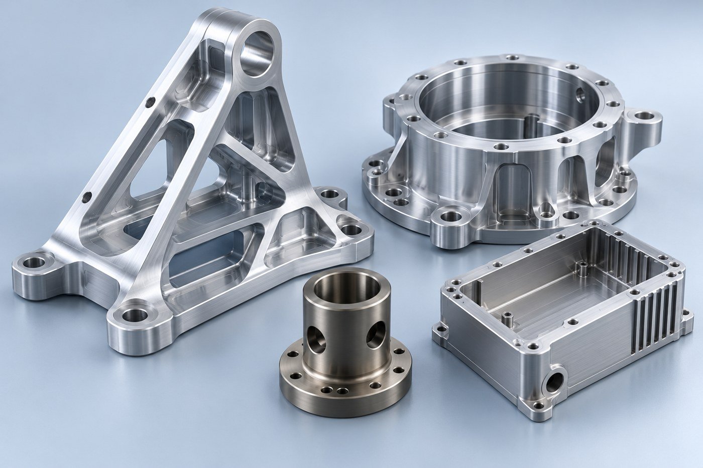
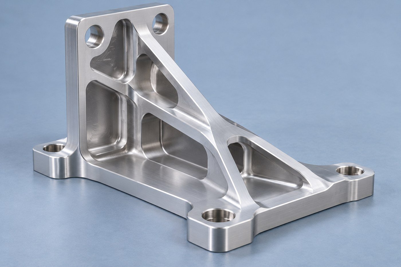
Pocketed brackets and support frames combine mounting faces, hole patterns and local stiffness features. Review the load-carrying geometry together with cutter access, remaining wall thickness and the method used to hold the part during machining.
Provide the permitted corner radii and the surfaces that must retain their full definition after deburring or finishing. Lightening pockets should follow the approved design rather than a general instruction to reduce mass.
- Equipment support brackets and mounting feet
- Adapter plates and interface frames
- Development hardware and assembly supports
Flanges and circular housings
Register diameters, bolt circles and seating faces need a coordinated datum scheme. Define their relationship to the mating assembly, including fit, orientation and any required runout or positional controls.
Shafts, sleeves and spacers
Turned parts can establish distance, alignment or rotational interfaces. Specify shoulder geometry, mating diameters, thread details and the condition in which the finished part will be inspected.
Fixtures and support tooling
Assembly nests, inspection supports and test fixtures need their own acceptance definition. Include contact points, replaceable elements, locating features and the workpiece envelope needed to establish access.

ELECTRONICS & EQUIPMENT INTEGRATION
Machined housings with defined assembly interfaces
Avionics and instrumentation enclosures may combine board supports, connector openings, cover patterns and mounting features in one part. Review internal clearance and assembly access alongside the external envelope.
Identify functional contact areas separately from cosmetic surfaces. If bonding, shielding, sealing or thermal interfaces are required, include the relevant surface and coating requirements in the controlled drawing.
A machined enclosure alone does not establish environmental, electromagnetic or thermal qualification. The equipment program defines the completed assembly’s acceptance and test requirements.
PROJECT CONTEXT
Share where the component fits in the development cycle
Development and fit-check builds
Early hardware can help evaluate assembly access and interface geometry. State which materials, finishes and dimensions must represent the eventual design, and which features are intentionally simplified for the evaluation.
Avionics and instrument integration
Mounting plates, enclosures and mechanical adapters need defined relationships to electronics and adjacent hardware. Supply connector envelopes, service clearances and installation datums when they control the component.
Ground support and test equipment
Fixture bases, adapter blocks and equipment supports can require precise locating features and durable identification. Distinguish tooling requirements from those of the article being assembled or tested.
Program-controlled component orders
For hardware intended for a qualified application, submit the full purchasing requirements and approval conditions. Manufacturing feasibility, supplier eligibility and documentation scope must all be resolved before order acceptance.
DESIGN FOR MANUFACTURING
Resolve the details that drive machining risk
Thin walls and deep pockets
Long tool reach and unsupported material can complicate cutting and measurement. Define minimum walls, corner radii and permissible edge treatment. Review setup strategy without changing the approved geometry silently.
Datum transfer between setups
Features on several faces need a clear relationship to the same functional references. Identify which characteristics control assembly so the machining sequence and inspection plan can preserve those relationships.
Finishing and final acceptance
Coatings and thermal processes can affect dimensions or surface condition. Specify masked areas, final-size requirements and the stage at which each critical characteristic is measured.
A dimensional tolerance, surface texture limit and geometric tolerance control different aspects of a part. Define each where needed rather than replacing them with a general “aerospace precision” note.
MATERIALS & PROCESS DEFINITION
Specify more than the alloy name
Material selection belongs to the component design. A quotation should identify the full material specification, condition, stock form and required records. The following families are options for project review, not a declaration that every grade or approved source is available.
| Material family | Component enquiries | Information to establish |
|---|---|---|
| Aluminum 6061 | Equipment housings, mounts and specified support hardware | Temper, stock form, material specification, finish and critical dimensions |
| Aluminum 7075 | Drawing-specified structural or mounting components | Required temper, product form, procurement restrictions and finishing requirements |
| Titanium alloys, as specified | Specialized interfaces and components subject to feasibility review | Exact alloy and condition, sourcing documentation, geometry and process requirements |
| Stainless and alloy steels | Shafts, pins, sleeves and specified mechanical hardware | Grade, heat-treatment condition, hardness requirements and final machining sequence |
| Engineering polymers | Specified guides, insulating elements and support parts | Exact resin and reinforcement, environment, conditioning and documentation |
Finishing as part of the drawing
Include the applicable treatment specification and revision, coverage, thickness where relevant, masking and acceptance requirements. If the program mandates an approved processor, state that condition in the RFQ.
Do not assume two finishes are interchangeable because they look similar. Substitutions need review against the controlled requirements.
Material records and identification
Define the records required with the supplied stock and finished component. Agree on how part identification and lot references should connect to the order documentation.
Marking location and method matter on thin walls, contact faces and appearance-sensitive areas; specify them rather than leaving them to interpretation.
DRAWING PARAMETERS
Make critical requirements measurable
The numerical entries below illustrate specification format only. They are not recommended aerospace design values, universal machining limits or guaranteed MileMetal capabilities. The complete drawing and quotation establish feasibility and acceptance.
| Characteristic | Illustrative entry | Additional definition |
|---|---|---|
| Critical linear dimension | 50.00 ±0.05 mm | Feature, datum relationship and acceptance condition |
| Mounting-face flatness | 0.05 mm on the designated face | Face boundary, support or restraint condition and process stage |
| Surface texture | Ra 1.6 μm on a marked surface | Measurement direction, area and any further texture requirement |
| Locating-hole pattern | Position tolerance relative to specified datums | Hole sizes, pattern definition and applicable drawing convention |
| Threaded connection | Full thread designation and usable engagement | Class, gauge requirement, entry detail and finish allowance |
| Pocketed structure | Wall, floor and internal-radius dimensions in mm | Permitted geometry variation, edge treatment and inspection access |
| Surface treatment | Specified process and controlled revision | Coverage, masking, final-size condition and required process records |
Apply close control to features that need it. Overly tight general tolerances can add cost without improving the assembly, while an undefined locating feature can leave a functional requirement unresolved.
FROM DRAWING PACKAGE TO DELIVERED PARTS
A clear manufacturing and verification sequence
Submit the definition
Provide controlled models, drawings, material, quantities and the complete purchasing requirements.
Resolve the scope
Review geometry, material sourcing, finishing, approvals, inspection and delivery expectations.
Produce to revision
Manufacture against the released definition with the agreed sequence and checks on designated characteristics.
Verify and protect
Complete the specified inspection records, identification and packaging before delivery.
Milling and multi-face features
Pockets, ribs, mounting faces and hole patterns drive workholding and tool access. Review the part’s complete geometry to establish a practical sequence, particularly when several surfaces share tight relationships.
Turning and concentric interfaces
Flanges, sleeves and stepped parts require coordinated dimensions between diameters and shoulders. Secondary holes, flats or finishing operations should be included in the quotation scope.
INSPECTION & TRACEABILITY
Plan the evidence alongside the component
Identify required measurements and documents before manufacturing begins. Some features are accessible only at an intermediate stage; others must be accepted after finishing. The inspection sequence should reflect that difference.
- Dimensions and geometry: characteristics, datums, methods and inspection conditions.
- Material definition: specified grade, condition and required source records.
- Process evidence: treatment documents and approved-source requirements where applicable.
- Configuration: part number, drawing revision and approved deviations.
- Delivery condition: identification, surface protection and agreed records.
Request CMM reports, gauges, sampling or other verification methods according to the characteristic. A generic inspection statement is not a substitute for the program’s acceptance requirements.

FIRST ARTICLE & REPEAT ORDERS
Separate a first-part check from a defined FAI package
The IAQG 9102 standard addresses a standardized first article inspection process and documentation for product verification. If your order requires a 9102-based FAI package, state the applicable requirements and agree on deliverables before production. See the IAQG 9102 overview.
An ordinary dimensional report should not be assumed to meet a specified FAI requirement. Confirm supplier eligibility, reporting scope and required supporting evidence as part of the order review.
| Stage | Information to control | Deliverable to agree |
|---|---|---|
| Quotation | Design revision, purchasing requirements and required approvals | Resolved assumptions and defined manufacturing scope |
| Initial production | Design characteristics and verification sequence | Specified first-part or first article records |
| Process or design change | Changed features, materials, sources or operations | Approval and required re-verification |
| Repeat batch | Released definition and lot identification | Agreed inspection and traceability records |
| Shipment | Protection, identification and document completeness | Packaging and the required delivery documentation |
START WITH THE FULL RFQ PACKAGE
Discuss your aerospace component requirements
Send the part files together with the material, finish, qualification and inspection requirements that govern the order. MileMetal can review the proposed machining scope and clarify what is needed for a quotation.
PROJECT QUESTIONS
Aerospace CNC machining FAQs
Which components can I submit for review?
Submit drawings for brackets, mounting parts, housings, flanges, sleeves, spacers and support tooling. Feasibility depends on the actual geometry, material, processes and purchasing requirements. Qualification for a specific program must be confirmed separately.
Can I start with development prototypes?
Include the evaluation quantity and the purpose of the build. Identify which dimensions, materials and finishes must represent the intended design. The quotation will establish the scope and any agreed differences from production hardware.
Does this page confirm aerospace certification or flight approval?
No. Provide the certifications and approvals required by your program and verify eligibility before ordering. The information and illustrations on this page are not evidence of certified status or authorization for installation in a flight application.
Can I request a first article inspection report?
Specify the required format, standard where applicable, characteristic coverage and supporting documentation in the RFQ. Confirm availability and scope before production. A routine first-part dimensional check is not automatically a complete FAI package.
Can materials or finishes be substituted?
Only through the approval process that governs your order. A similar alloy, temper or coating is not automatically equivalent to the drawing requirement. Record approved changes in the controlled file set or authorized deviation.
How should thin-wall parts be specified?
Define the minimum wall and floor dimensions, internal radii, critical surfaces and inspection restraint condition. Share any mass or stiffness constraints so proposed manufacturing changes can be reviewed by the responsible designer.
Are the images examples of delivered flight hardware?
No. They are concept illustrations of component geometry and inspection activities. They do not represent a customer project, a qualified design or delivered flight hardware.
What should accompany a repeat order?
Confirm the released model and drawing revision, material, finish, required records, quantity and delivery target. Include approved changes and identify any re-verification required by the order or program.
Turn your component definition into a clear machining scope
Bring the drawing and the purchasing requirements together from the beginning.