
MILEMETAL · AUTOMOTIVE
CNC Machining for Automotive Components
Move your automotive component design into a practical first build. MileMetal reviews custom housings, brackets, shafts, adapters and fixture parts for drawing-based machining.

A useful prototype starts with a clear purpose
An automotive development part might be needed to check packaging, evaluate an assembly process or support a test rig. Those are different jobs. A part made only for a fit check may not need the final material, while a test component may need to reproduce the intended interfaces and finished condition closely.
Tell us what the build needs to demonstrate. We can then review the geometry and quotation scope around that objective, including the dimensions, surfaces and records that need attention. For production programs, include the purchasing and supplier-approval requirements at the start.
Review the housing as part of the assembly
A component housing can combine bearing or shaft interfaces, cover joints, mounting points and access openings. These features should be reviewed together. A correct outside envelope does not tell you whether the internal components can be inserted or whether the fasteners can be reached.
Send the relevant mating CAD when it helps explain the installation. Mark the surfaces that locate the assembly, seal a joint or contact another part. This makes it easier to distinguish functional requirements from general cosmetic surfaces.
If a prototype represents a future casting, identify which features must carry through to that process. A fully machined development part may be useful for evaluation, but the later production route should be considered in the design release.

FROM THE MILEMETAL MEDIA LIBRARY
Part forms and the work behind them
These existing product and workshop photographs show relevant geometries and manufacturing activities. They are separate examples, rather than a single customer project.

Machined component geometry
A component example with slots, holes and several machined faces.

Circular housing interface
A circular housing example with an internal bore and external ribs.

Shaft and pin components
Shaft and pin examples showing turned diameters and thread details.

Mounting flange
A flange example with a repeated fastener pattern.
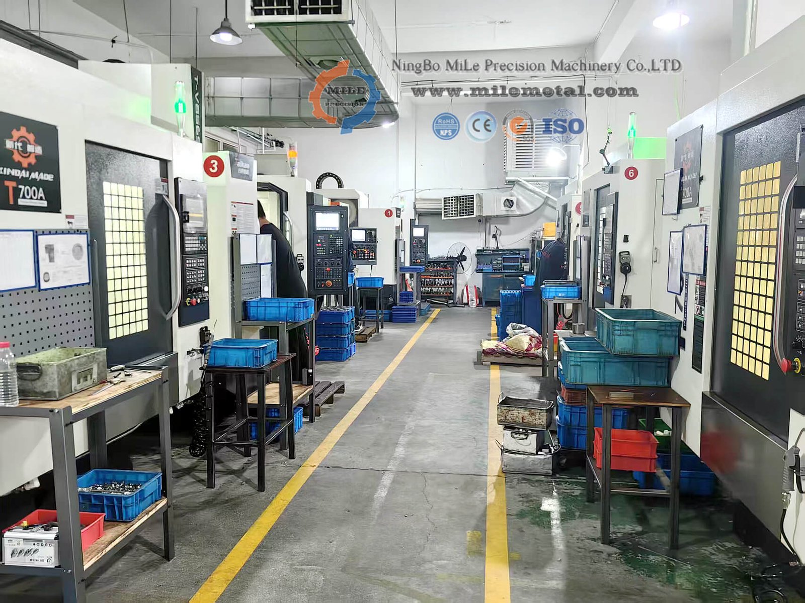
Machining workshop
Production equipment from the MileMetal media library.

Dimensional inspection
CMM inspection examples from the MileMetal media library.
Support for the next stage of development
Packaging and fit checks
Machined housings, adapters and brackets can help teams evaluate real interfaces before a larger commitment. State any deliberate departures from the intended production design.
Test and development equipment
Fixture parts and mounting hardware should reflect the loads, clearances and measurement access required by the test setup.
Program-controlled supply
Send the complete quality and supplier requirements with the RFQ. Confirm qualification and documentation scope before placing a production order.
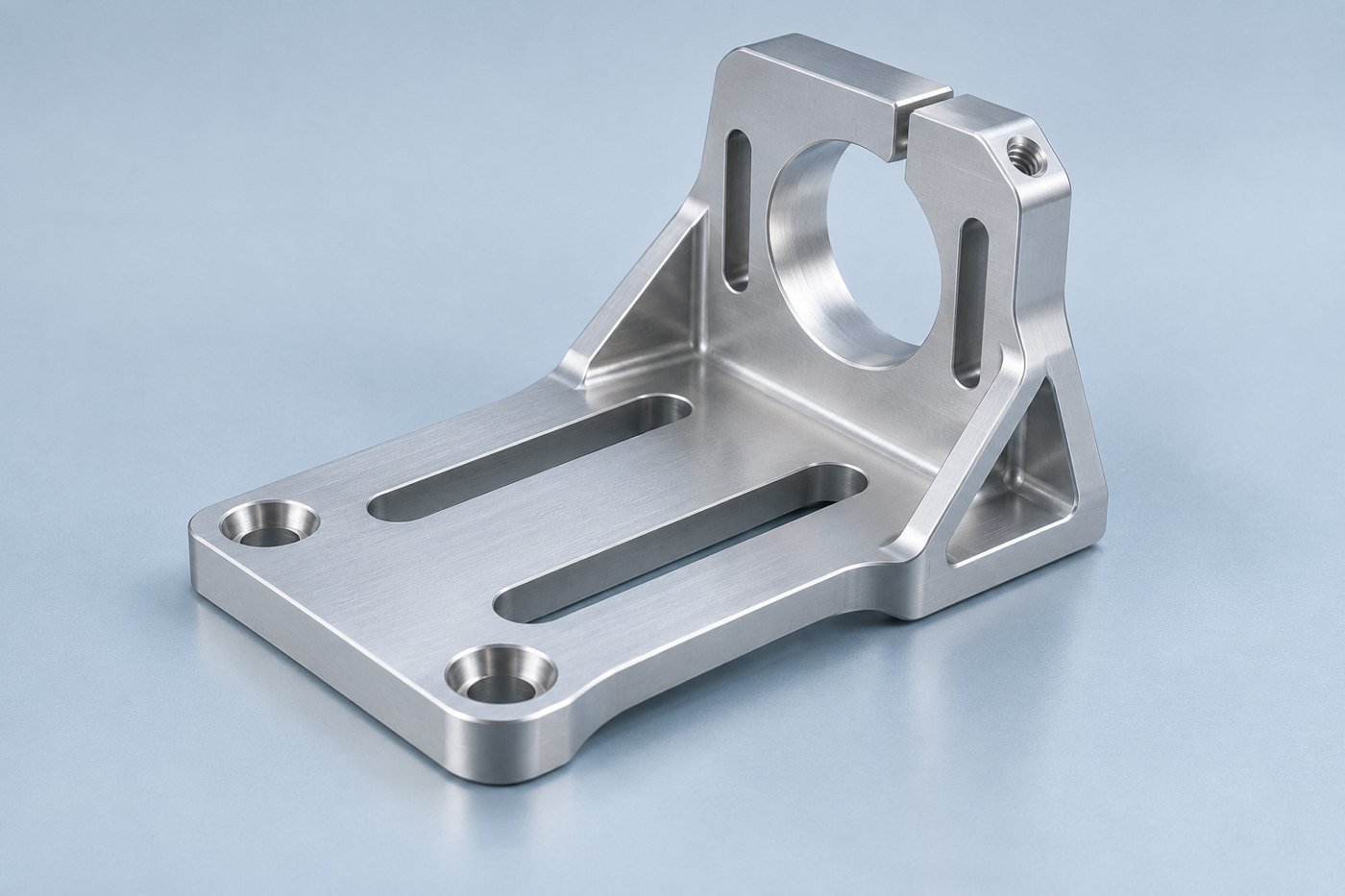
Small brackets can carry important alignment requirements
Sensor mounts and equipment brackets are often straightforward to machine, yet their hole patterns and seating faces can determine where another component ends up. Establish the locating features and the adjustment range instead of relying on fastener clearance to describe both.
Slots should have a stated purpose: adjustment, installation access or a connection to another part. Include the surrounding envelope so a proposed shape can be checked against nearby hardware and service tools.
For coatings, identify the surfaces that need masking or final-size control. A finish that improves appearance may still need special treatment at a locating face or electrical contact.
Choosing the material and finish
Choose the material around the purpose of the build. A packaging sample and a mechanically representative test part may need different definitions. If a substitution is proposed for a prototype, record it explicitly so the result is not mistaken for a test of the final design.
| Material to discuss | Typical component enquiry | Details to include |
|---|---|---|
| Aluminum 6061 or drawing-specified alloy | Prototype housings, mounts and adapters | Define temper, functional faces and finish. |
| Alloy or carbon steel | Shafts, pins, spacers and fixture parts | Specify grade, hardness, treatment sequence and finished dimensions. |
| Stainless steel | Selected hardware and interfaces | State exact grade, exposure and required surface condition. |
| Engineering polymers | Guides, spacers and fixture contact elements | Provide resin grade, load, temperature and dimensional needs. |
Material availability and process scope are confirmed against your drawing and quotation. Include any restrictions on substitutions or approved sources.
The drawing details worth resolving early
Use the component’s function to decide what needs close control. The following details give the machining and inspection review a useful starting point.
| Feature | What to define | Why it helps |
|---|---|---|
| Housing register | Fit and datum relationship | Defines how the mating component is located. |
| Bracket mounting pattern | Hole sizes, position and adjustment range | Controls placement without hiding the function in a general tolerance. |
| Finished shaft | Journal sizes, shoulders and required geometric controls | Relates the critical interfaces after all specified processing. |
| Test fixture | Locating scheme, clamps and measurement access | Makes the setup repeatable and usable. |
| Program documentation | Required records, sample scope and approvals | Allows the quotation to include the actual acceptance work. |
Build measurement and assembly access into the fixture
A fixture works best when its locating scheme is easy to understand and repeat. Show the contact points, the clamping sequence and the workpiece condition. Avoid leaving the operator to decide which surface should be pushed against a stop.
For a development fixture, replaceable nests or pins may make later changes easier. Describe those interfaces and the expected adjustment range in the drawing package. The fixture should allow access to the features that need inspection or assembly.
Keep fixture revisions linked to the part revision they support. When the product changes, review the locating and clamping features before reusing the old tooling.

Separate part inspection from system validation
A dimensional report can show whether the component meets its drawing. It does not establish the performance of the complete vehicle system. Define the material, geometry and process requirements needed for your build, then evaluate the assembled design under its own test plan.
For orders requiring specific submission packages or approved sources, provide the complete requirements before quotation. Do not assume that a generic inspection report or a development sample meets a production program’s approval process. This page does not claim automotive quality-system certification or approval for safety-critical applications.
Put numbers where they help the drawing
Clear callouts are easier to quote and inspect than a general request for “high precision.” The examples below show the format of a requirement, not recommended design values or a guarantee of machining capability.
| Characteristic | Illustrative format | Complete the definition |
|---|---|---|
| Critical size | 25.00 ±0.05 mm | Identify the feature and the condition in which it is accepted. |
| Surface texture | Ra 1.6 μm on a marked face | Define the area and any measurement requirements. |
| Flatness | 0.05 mm over a designated face | State the support condition and whether acceptance follows finishing. |
| Thread | Full designation, class and usable depth | Include blind-hole clearance and the required finished condition. |
Where the design depends on a purchased bearing, connector, motor or other mating part, include that interface information. It is usually more useful than tightening unrelated dimensions across the entire component.
A straightforward way to start
Send a STEP model and a dimensioned drawing with the material, finish, quantity and delivery needs. Add an assembly view when it explains a fit or an access constraint. We can then review the component and identify the open details needed for a quotation.
Before production, agree on the released revision, any secondary operations and the inspection records to be supplied. After a first build, keep approved changes in the same controlled file set. This gives the next order a clear starting point instead of a trail of disconnected notes.
Questions before your first order
Can you quote automotive prototypes?
Yes. Send the drawing package, quantity and build objective. Explain which materials and interfaces must represent the intended production design.
Can a machined prototype represent a future casting?
It can support some development objectives, but the differences between the two routes need review. Identify the features and material properties that matter to the evaluation.
Do you supply inspection records?
Specify the characteristics, format and sampling you need. Any program-specific submission or approval requirements should be included before the order is accepted.
Can you machine sensor brackets and adapters?
Send the mating geometry, mounting pattern and installation envelope along with the component drawing. Define any adjustment or locating features clearly.
Do the gallery images prove an OEM approval?
No. The gallery illustrates existing part forms and machining or inspection scenes. It is not evidence of a customer nomination or program approval.
How should I prepare a follow-on order?
Release the updated model and drawing together, confirm material and finish, and identify any changed inspection requirements. Keep deliberate prototype deviations separate from the production definition.
START A CONVERSATION
Tell us what your next automotive build needs to prove
Share your drawing package and tell us which parts you need first. Include the features that matter to the assembly so the quotation can address the work you actually need.