
PRECISION PARTS FOR EQUIPMENT BUILDERS
CNC Machining for Medical Device Components
Custom machined housings, mounting parts, adapters and mechanical interfaces for medical equipment, diagnostic instruments and laboratory systems.
Bring your component drawings to MileMetal for a review of material, geometry, finishing and inspection requirements. Establish a clear manufacturing scope for your first build and the repeat orders that follow.
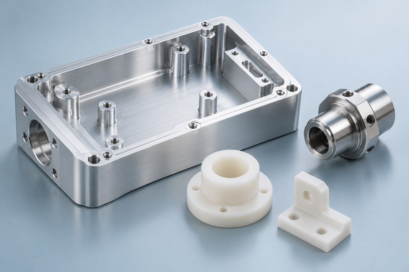
COMPONENT MANUFACTURING SCOPE
Make the mechanical requirements clear from the start
Medical equipment brings together electronics, sensors, motion systems and fluid interfaces. Its machined parts must fit the surrounding assembly and arrive with the specified surface condition and records. A useful quotation starts with the intended role of each component, not simply its overall size.
Equipment and instrument hardware
This page focuses on non-implant equipment components: enclosures, supports, mounts, spacers and mechanical interfaces. Include the service environment and any contact or cleanliness requirements that affect the component definition.
State whether a part is internal, user-accessible, exposed to cleaning agents or part of a fluid path. These distinctions help identify the information needed before production.
A defined supplier scope
Identify required supplier qualifications, material records and acceptance procedures in the RFQ. Confirm availability before placing an order. The device manufacturer establishes intended use and the finished device’s qualification requirements.
A machining quotation does not by itself establish biocompatibility, sterility or suitability for a clinical application.
TYPICAL COMPONENT TYPES
From instrument housings to precision interfaces
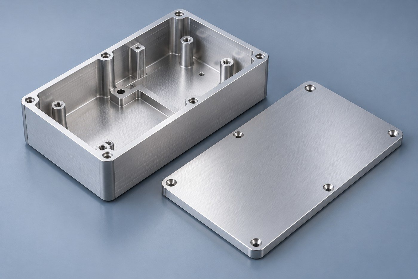
Housings, covers and internal frames
Custom enclosures locate circuit boards, sensor modules and mechanical assemblies. Pockets, mounting bosses, connector openings and cover patterns should be reviewed as one system of interfaces.
Provide board outlines, connector envelopes and installation clearances when they control the design. Distinguish sealing or locating faces from surfaces that only need an appearance finish.
- Diagnostic instrument chassis and enclosure parts
- Sensor-module housings and mounting plates
- Equipment covers and internal structural supports
Brackets & positioning parts
Mounting brackets, reference plates and standoffs support optics, sensors, motors and other modules. Define which surfaces locate the assembly, which fasteners retain it and what access is needed for installation or service.
Shafts, bushings & spacers
Turned parts can provide bearing interfaces, spacing and guided motion. Specify mating diameters, shoulder relationships, thread details and finished condition rather than relying on a generic tolerance note.
Guides & insulating elements
Machined polymer guides, bushings and spacers can separate or support components. Define the exact resin grade and the load, temperature and chemical environment that influence the design.
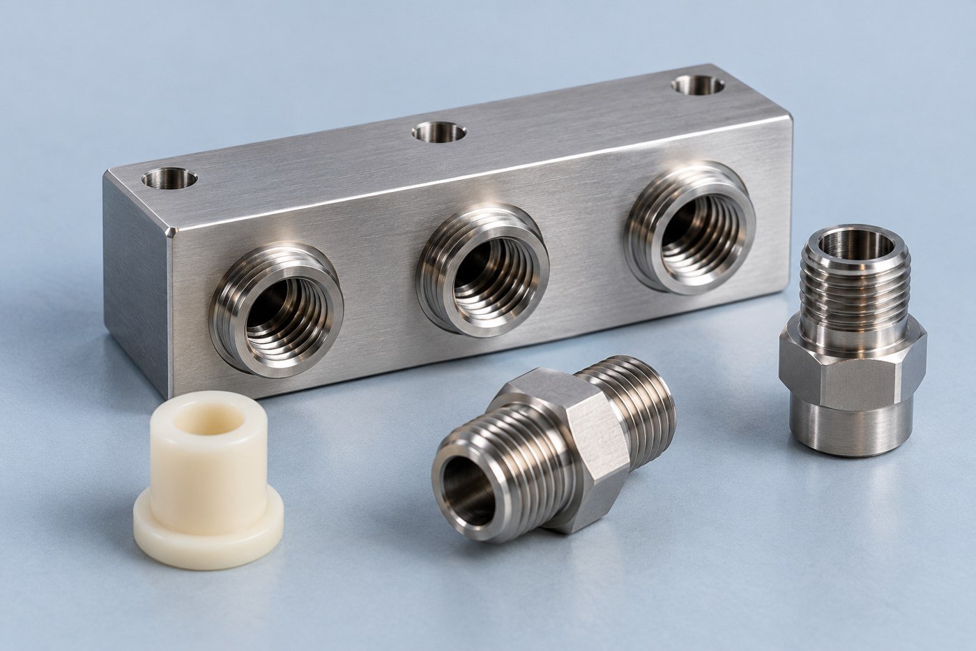
FLUID & CONNECTION HARDWARE
Define the full interface, not just the thread
Adapter bodies and manifold blocks can combine passages, ports, closure features and seal seats. Their drawings should define how each connection seals and how internal intersections will be accessed for deburring and inspection.
Identify wetted surfaces, the fluid involved and any cleaning or residue limits. If a connection has patient contact or another special use requirement, provide that context and the applicable specifications before requesting a quotation.
Leak testing, assembly and specialized cleaning must be listed explicitly in the order scope. A machined component or concept image does not establish a qualified fluid system.
EQUIPMENT APPLICATIONS
Different instruments need different review priorities
Diagnostic and analytical instruments
Housings, sample-handling supports and sensor mounts can have several alignment relationships within a compact envelope. Share mating CAD and identify the reference features that establish the measurement assembly.
Laboratory automation
Fixture plates, motion supports and instrument adapters need defined installation and service access. Review locating pins, bolt patterns, moving clearances and replacement-part requirements together.
Monitoring equipment hardware
Enclosures, mounting accessories and internal brackets may combine visible surfaces with close-fitting features. Separate cosmetic criteria from dimensional acceptance, and identify cleaning exposure where relevant.
Imaging and positioning equipment
Structural plates and mechanical interfaces should be reviewed against their loads, alignment requirements and surrounding environment. Supply any application-specific restrictions on material or finish instead of assuming a general-purpose alloy is suitable.
ENGINEERING REVIEW
Address fit, finishing and inspection before machining
Assembly references
Choose datums that reflect how the part is installed. A face that is convenient to measure may not be the surface that establishes the actual assembly position. Identify critical hole patterns, bores and contact areas clearly.
Geometry and access
Deep pockets, small internal radii and thin walls can increase tool reach and workholding demands. Provide permissible radii and edge treatments, and review any proposed geometry change before it enters the released drawing.
Final surface condition
Finishing may affect fits, texture and visual appearance. Specify protected features and the stage at which critical dimensions are accepted. Cleaning and handling requirements should accompany the geometric definition.
Manufacturing feedback supports the component review. Changes to material, function or application requirements remain subject to the customer’s design approval.
MATERIALS & FINISHES
Specify the grade and the conditions it must meet
Material names alone do not define application suitability. Include grade, condition, stock requirements and the documentation needed for your device program. The options below are starting points for a manufacturing discussion, subject to project review.
| Material option | Component types to discuss | Information to provide |
|---|---|---|
| Aluminum 6061-T6 | Instrument housings, brackets and internal frames | Finished dimensions, anodizing specification, masked areas and cosmetic criteria |
| Aluminum 7075-T6 | Specified structural or mounting components | Required condition, loading environment, finish and any material restrictions |
| Stainless steel 304 / 316L | Adapter bodies, supports and specified equipment interfaces | Exact alloy, exposure conditions, surface treatment and material records |
| PEEK, specified grade | Specialized insulating supports, bushings and equipment parts | Resin designation, reinforcement, temperature, chemical exposure and documentation |
| POM / acetal, specified grade | Guides, spacers and selected moving components | Dimensional stability needs, loading, service environment and cleaning exposure |
| Other drawing-specified materials | Application-dependent metal or polymer components | Full specification and purchasing restrictions for feasibility and stock review |
Surface finishing
Discuss anodizing, bead blasting, polishing or specified stainless treatment as separate process requirements. Define the surfaces involved, permitted texture and final-size condition. An attractive finish does not demonstrate a particular cleanliness or biological performance level.
Cleaning and packaging
Replace a general “clean parts” note with an agreed method and acceptance definition when cleanliness matters. Specify drying, residue limits, handling and packaging. Sterilization or sterile-barrier packaging requires a separately defined and qualified scope.
DRAWING & RFQ PARAMETERS
Write requirements that can be manufactured and checked
The numerical entries below are examples of specification format, not recommended device design values or guaranteed MileMetal capabilities. Feasibility and acceptance are confirmed from the complete drawing and order requirements.
| Requirement | Illustrative entry | Also define |
|---|---|---|
| Critical size | 30.00 ±0.05 mm | Feature, datum relationship and inspection condition |
| Mounting-face flatness | 0.05 mm on the identified face | Area boundary, support condition and acceptance before or after finishing |
| Surface texture | Ra 1.6 μm on a marked surface | Measurement area, direction and any further texture requirement |
| Threaded mounting hole | M4 × 0.7 with specified class and usable depth | Entry detail, blind-hole clearance, gauge requirement and coating allowance |
| Polymer component | Exact resin grade and dimensional limits | Conditioning or measurement environment where required |
| Internal passages | Passage dimensions, intersections and port definitions | Deburring access, cleaning method and test scope |
| Identification and records | Part number, revision and required lot reference | Marking location, report format and agreed traceability depth |
Assign tighter control to the features that determine function. A generic “high precision” note cannot replace a clear locating scheme, surface requirement or fit definition. Where the model and drawing differ, establish the governing information before production release.
MANUFACTURING WORKFLOW
From component definition to an agreed delivery condition
Submit the files
Send STEP models, controlled drawings, material, quantity and delivery needs. Identify critical interfaces and program-specific requirements.
Review the scope
Resolve geometry, stock, finish and inspection questions. Confirm required supplier documentation and any secondary operations.
Machine & finish
Produce to the released component definition and agreed sequence, with checks on the identified characteristics.
Verify & protect
Complete the agreed records and packaging so the delivered parts retain their specified condition.
Milling for complex interfaces
Pockets, faces, bosses and hole patterns can be machined into instrument housings and supports. Review setup access and the relationship between faces on different sides of the part.
Turning for cylindrical features
Adapter bodies, sleeves, shafts and spacers require a clear relationship between diameters, shoulders and threads. Secondary holes or flats may add another operation to the route.
QUALITY & DOCUMENTATION
Agree on evidence for the characteristics that matter
A dimensional report, a material record and a cleanliness result answer different questions. Define the documentation needed for your component and confirm the available scope before ordering.
- Geometry: critical sizes, locations, mating features and measurement conditions.
- Material: grade, condition and the records specified in the purchase requirements.
- Finish: texture, coating, protected areas and appearance acceptance.
- Identification: part number, drawing revision and agreed lot references.
- Delivery: packaging, protection and the required inspection documents.
Specify CMM reports, thread gauges or other measurement methods where the characteristic requires them. Sampling and acceptance criteria should be agreed rather than inferred from a general inspection statement.
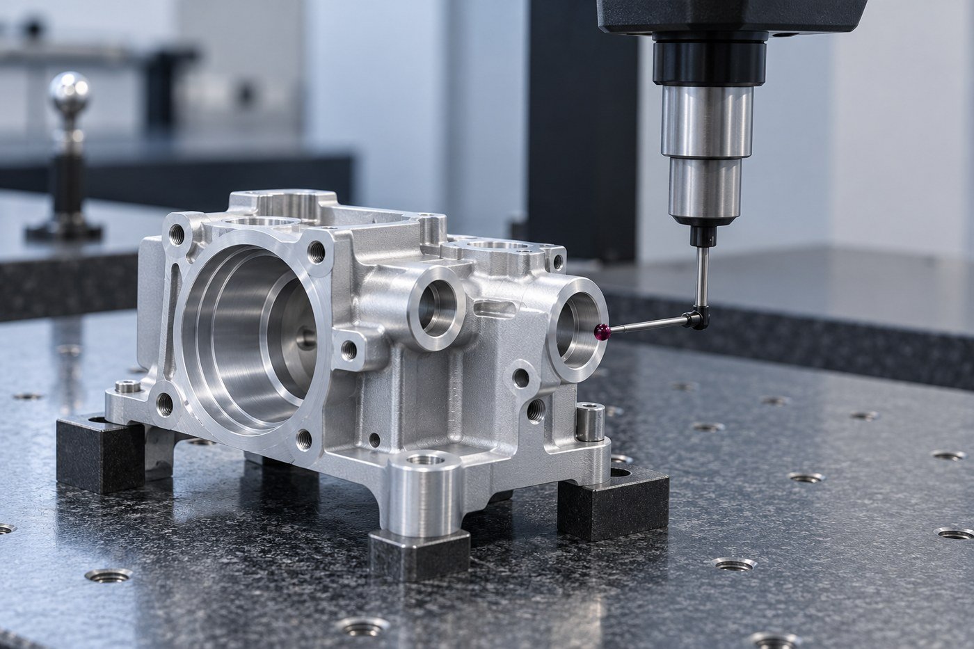
PLAN THE HANDOVER
Keep prototype learning connected to the released design
| Project stage | Information to control | Useful output to agree |
|---|---|---|
| Initial quotation | Model and drawing revision; material; scope; quantity | Resolved questions and defined quotation assumptions |
| First build | Critical interfaces and evaluation objectives | Specified first-part measurements and records |
| Design revision | Changed dimensions, materials or finishes | Approved file set and required reinspection |
| Repeat order | Released definition and any approved deviations | Agreed batch records and part identification |
| Shipment | Surface condition, protection and documentation | Inspection documents and specified packaging |
After evaluating the first parts, incorporate approved changes into the model and drawing together. Do not rely on a sample, email note or photograph to silently replace a controlled requirement. Clear revision control helps the next order match the design that was actually approved.
START WITH YOUR COMPONENT PACKAGE
Discuss your medical equipment machining project
Send the component files and explain the interfaces, documentation and delivery condition your equipment program needs. MileMetal can review the manufacturing scope and identify the details required for a quotation.
COMMON PROJECT QUESTIONS
Medical device component machining FAQs
What component types can I submit?
Send drawings for equipment housings, brackets, mounting plates, sensor supports, adapters, spacers and other mechanical parts. This page focuses on non-implant equipment hardware. Application-specific requirements should be provided with the RFQ for review.
Can I request prototype and repeat-order quantities?
Yes. Provide the first-build quantity and expected future demand together. The quotation will define the available manufacturing scope, schedule and inspection requirements for the actual component.
Is a material automatically suitable because it is called medical grade?
No. Provide the precise grade and the documentation or qualification requirements for the intended use. Application suitability depends on more than a generic material name, including processing, surface condition and the finished component’s use.
Can the parts be supplied with inspection documentation?
List the required characteristics, report format, sampling and material records before ordering. The agreed scope determines the supplied documents. Confirm any special qualification or traceability requirement before production release.
Does the service include sterilization or sterile packaging?
Do not assume these are included in a component machining quote. If needed, provide the required processes and qualification evidence for separate review. Ordinary cleaning and protective packaging are different from a sterile supply requirement.
How are critical fits handled after coating?
The drawing should identify which dimensions apply after finishing and which areas require masking or other control. Review coating allowances, measurement stage and mating-part requirements before approving the process.
Do the illustrations show delivered customer products?
No. They are concept illustrations of component types and inspection activities. Your quotation and released drawings define the parts to be manufactured; the images do not represent a validated device or customer project.
What is the best way to start a quote?
Send the model, controlled drawing, material, finish, quantities and delivery needs. Add intended component use, required supplier qualifications and documentation. Include mating geometry wherever it controls fit or inspection.
Make your next component build easier to specify
Share the drawing package and acceptance requirements before production starts.