
MILEMETAL · ENERGY
CNC Machining for Energy Equipment Components
From a power-electronics enclosure to an instrument adapter, energy equipment depends on mechanical parts that fit their surroundings. Bring MileMetal your drawings for custom housings, thermal interfaces, mounting hardware and turned components.
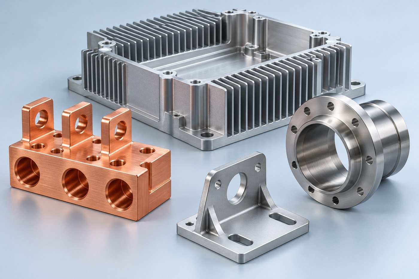
Start with the interface, then define the component
Energy equipment covers very different working environments. A part inside a clean electrical cabinet faces a different set of demands from a bracket installed outdoors or a fitting exposed to a process fluid. The useful starting point is the part’s job: what it supports, what it touches and what the surrounding system expects it to do.
We welcome drawing-based enquiries for components used in power conversion, energy storage equipment, monitoring instruments and supporting machinery. Tell us whether the order is for a development build, a replacement or repeat production. That context helps put the right attention on interfaces, finishing and inspection before manufacturing begins.
Make the thermal and electrical interfaces explicit
A thermal plate may look simple until the mating surfaces are considered. The position of the heat source, the clamping pattern and the thickness of the interface material all influence which faces need careful control. Show those faces on the drawing and identify the condition in which they will be measured.
For a conductive component, include the material grade and the surface treatment expected at each contact. A coated exterior and an uncoated contact area are different requirements and should be marked separately. Where a terminal or fastener locates the part, provide the mating geometry rather than leaving the manufacturing team to infer it from a photograph.
A machined heat spreader or connector is one element of a larger assembly. Share the component requirements that follow from your electrical and thermal design, and reserve the system-level acceptance criteria for the appropriate assembled-product tests.

FROM THE MILEMETAL MEDIA LIBRARY
Part forms and the work behind them
These existing product and workshop photographs show relevant geometries and manufacturing activities. They are separate examples, rather than a single customer project.
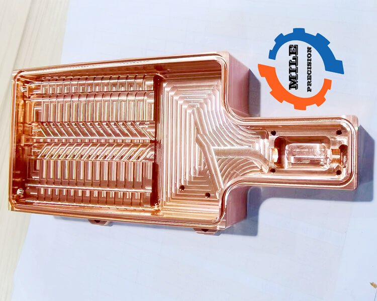
Copper component with detailed channels
A copper part with densely machined surface features and peripheral interfaces.

Circular copper components
Circular copper forms with a central opening and a patterned face.

Formed conductive hardware
Metal hardware combining bent profiles with connection holes.

Threaded brass adapters
Turned brass components with external threads and wrenching features.

Pocketed aluminum plate
A machined plate with channels, pockets and mounting details.

Instrument panel
A panel example with openings for controls and interfaces.
Where these components fit
Power conversion equipment
Housings, contact components and mounting plates connect electrical packaging with mechanical assembly. Include cable, connector and service envelopes where they affect the part.
Energy monitoring and instrumentation
Sensor bodies, adapters and support hardware need clearly defined connections. Explain the sealing method and exposure conditions when they influence the drawing.
Storage and supporting equipment
Brackets, covers, spacers and fixture parts can support development and production builds. Distinguish functional interfaces from features intended only for clearance.
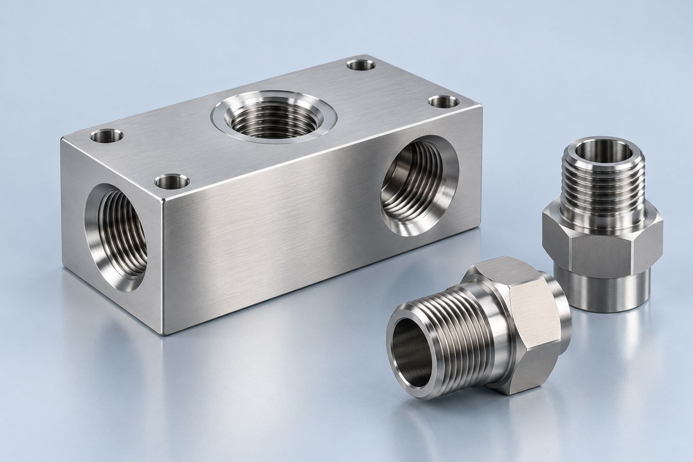
Adapters and instrument bodies need a complete connection definition
Instrument bodies, manifold blocks and threaded adapters bring several interfaces into a small space. A thread designation alone may not describe the sealing arrangement. Identify the seat, sealing face or seal groove, and provide the relevant connection specification or mating-part information.
Cross-drilled passages also deserve attention. State where burr control, internal cleanliness and inspection access matter. If the part requires a pressure or leak test, agree on the medium, test conditions, acceptance criteria and documentation before ordering. These requirements should be quoted as defined operations.
Avoid treating every adapter as a pressure-rated product by default. The drawing, selected material, manufacturing scope and validation plan need to match the intended service. A clear request makes it easier to distinguish machining work from assembly and testing work.
Choosing the material and finish
Material selection should follow the component’s electrical, thermal and mechanical duties. Specify the actual alloy or polymer grade and any required records. An application name such as “energy storage” is not a substitute for the conditions at the part.
| Material to discuss | Typical component enquiry | Details to include |
|---|---|---|
| Aluminum, specified alloy and temper | Enclosures, support plates and thermal housings | Define contact faces, coating, mounting loads and finished dimensions. |
| Copper, specified grade | Conductive parts and thermal interfaces | Include surface condition, plating, contact geometry and material records. |
| Stainless steel, specified grade | Instrument bodies and selected adapters | Describe fluid contact, exposure and required connection details. |
| Engineering polymer, specified grade | Insulating spacers and guides | Provide electrical, thermal and mechanical requirements for material review. |
Material availability and process scope are confirmed against your drawing and quotation. Include any restrictions on substitutions or approved sources.
The drawing details worth resolving early
Use the component’s function to decide what needs close control. The following details give the machining and inspection review a useful starting point.
| Feature | What to define | Why it helps |
|---|---|---|
| Contact face | Marked area, flatness and surface texture | Focuses control on the surfaces that transfer heat or current. |
| Fluid connection | Thread, seat, seal and mating specification | Removes ambiguity about how the joint is made. |
| Mounting pattern | Datum system and critical positions | Relates the part to the equipment rather than its outside shape alone. |
| Finishing | Coating type, masking and acceptance condition | Keeps contact and locating surfaces consistent with the design. |
| Internal passage | Deburring, cleaning and inspection requirements | Makes otherwise hidden operations part of the manufacturing scope. |
Think about installation as well as operation
Mounting plates and support brackets are often the last parts designed and the first parts noticed during assembly. Check fastener access, tool clearance and the space needed to remove a neighboring component. A small clearance change in the model can save a difficult installation later.
For outdoor or cabinet-mounted equipment, state the exposure conditions and the finish specification. Define which surfaces locate the assembly and which holes provide installation clearance. This keeps the drawing focused on fit instead of applying an unnecessarily tight tolerance to every feature.
When ordering service parts, include the released revision and any changes made during installation. A replacement should be based on the approved geometry, with wear or damage considered separately from the intended dimensions.
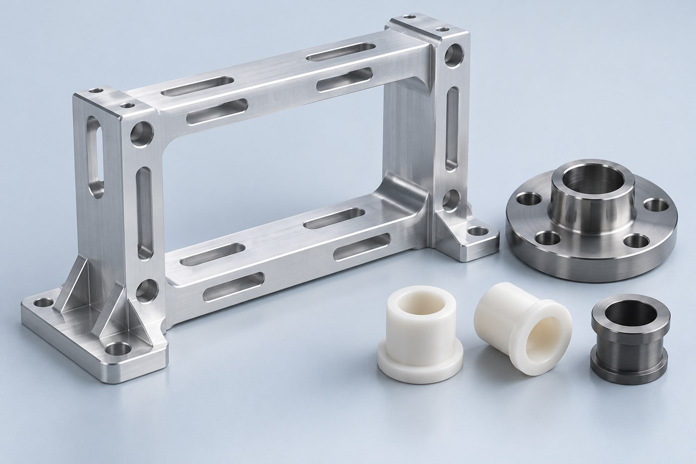
Inspection that follows the function of the part
Agree on the characteristics that will be reported before the first order. For a contact plate, this might include a designated face and mounting pattern; for an adapter, the connection and sealing geometry may be more useful than a general dimension list.
Material records, surface treatment documentation and defined tests should be included in the quotation when needed. The delivery package should make it clear what was measured or tested and which released drawing governed the work.
Put numbers where they help the drawing
Clear callouts are easier to quote and inspect than a general request for “high precision.” The examples below show the format of a requirement, not recommended design values or a guarantee of machining capability.
| Characteristic | Illustrative format | Complete the definition |
|---|---|---|
| Critical size | 25.00 ±0.05 mm | Identify the feature and the condition in which it is accepted. |
| Surface texture | Ra 1.6 μm on a marked face | Define the area and any measurement requirements. |
| Flatness | 0.05 mm over a designated face | State the support condition and whether acceptance follows finishing. |
| Thread | Full designation, class and usable depth | Include blind-hole clearance and the required finished condition. |
Where the design depends on a purchased bearing, connector, motor or other mating part, include that interface information. It is usually more useful than tightening unrelated dimensions across the entire component.
A straightforward way to start
Send a STEP model and a dimensioned drawing with the material, finish, quantity and delivery needs. Add an assembly view when it explains a fit or an access constraint. We can then review the component and identify the open details needed for a quotation.
Before production, agree on the released revision, any secondary operations and the inspection records to be supplied. After a first build, keep approved changes in the same controlled file set. This gives the next order a clear starting point instead of a trail of disconnected notes.
Questions before your first order
Can I request parts for a battery or inverter assembly?
Yes. Send the mechanical drawings, material and finish requirements, quantity and assembly context. Include electrical or thermal interface requirements that affect machining.
Do you select the conductive material for my design?
Provide the grade selected by your engineering team. If alternatives are being considered, identify the requirements and restrictions so they can be discussed before quotation.
Can a manifold or adapter be leak tested?
Include a defined test procedure or the required medium, conditions and acceptance criteria. The available testing scope and documentation must be confirmed in the quotation.
What information matters for a thermal plate?
Identify the contact surfaces, clamping arrangement, material, coating and dimensional acceptance condition. An assembly view helps explain the contact path.
Can prototype and repeat orders use the same drawing?
They can if the drawing describes the intended part at both stages. Record changes after evaluation and release a new revision when requirements change.
Should every feature have the tightest tolerance?
No. Identify the features that control fit or function. Keep clearance features and noncritical surfaces consistent with their actual purpose.
START A CONVERSATION
Let’s discuss your energy components
Share your drawing package and tell us which parts you need first. Include the features that matter to the assembly so the quotation can address the work you actually need.