
3D Laser Cutting for Metal Parts: Process, Parameters & Design Guide
2026-11-09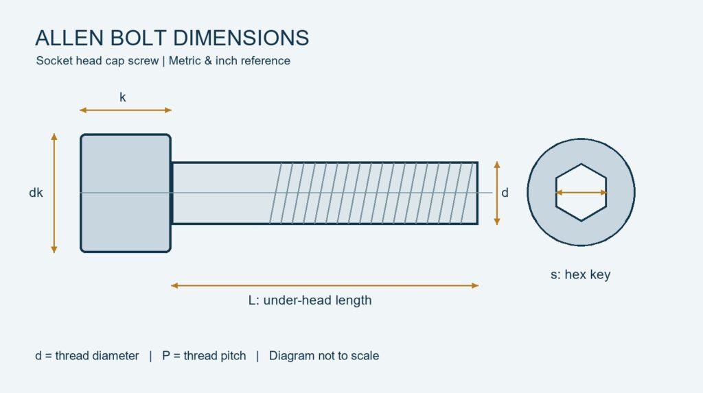
MILEMETAL · FASTENER & MACHINED PART DESIGN
Allen Bolt Size Chart: Metric & Inch Socket Head Cap Screw Dimensions
The size stamped on an Allen key is not the size of the screw. A standard M6 socket head cap screw takes a 5 mm hex key; an M8 takes a 6 mm key. Keeping those two measurements separate is the first step toward choosing the right fastener.
This guide brings together common metric and inch socket head cap screw dimensions, then explains how to use them when measuring a sample, designing a counterbore or preparing a purchase specification.
Jump to: Metric chart · Inch chart · Measuring a screw · Head types · Hole design · Torque · FAQs
Metric Allen bolt size chart
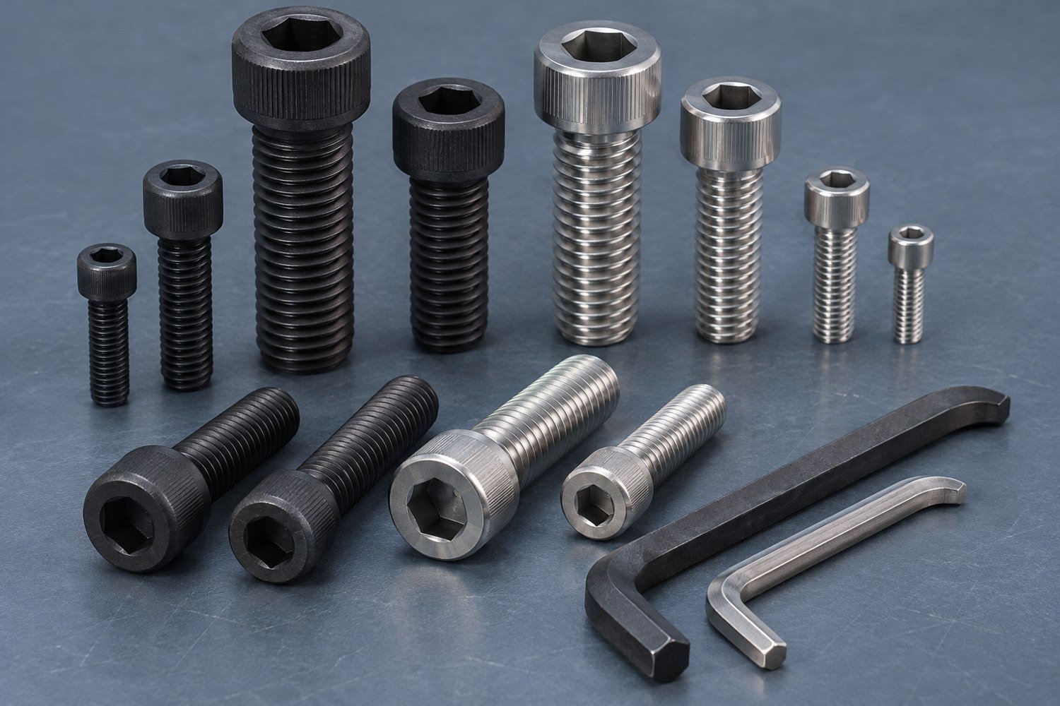
The table covers common coarse-thread, cylindrical socket head cap screws associated with ISO 4762 and DIN 912. All measurements are in millimeters. Head dimensions are reference maximums for the plain cylindrical head; the hex-key column gives the nominal tool size, not a manufacturing tolerance for the socket.
| Thread d | Coarse pitch P (mm) | Plain head diameter dk, max (mm) | Head height k, max (mm) | Hex key s (mm) |
|---|---|---|---|---|
| M2 | 0.4 | 3.8 | 2 | 1.5 |
| M2.5 | 0.45 | 4.5 | 2.5 | 2 |
| M3 | 0.5 | 5.5 | 3 | 2.5 |
| M4 | 0.7 | 7 | 4 | 3 |
| M5 | 0.8 | 8.5 | 5 | 4 |
| M6 | 1 | 10 | 6 | 5 |
| M8 | 1.25 | 13 | 8 | 6 |
| M10 | 1.5 | 16 | 10 | 8 |
| M12 | 1.75 | 18 | 12 | 10 |
| M14 | 2 | 21 | 14 | 12 |
| M16 | 2 | 24 | 16 | 14 |
| M20 | 2.5 | 30 | 20 | 17 |
| M24 | 3 | 36 | 24 | 19 |
Before using these figures for a drawing: check the purchased fastener’s standard, revision and manufacturer drawing. Knurling can increase the head envelope, and special or reduced-head designs can differ. This abbreviated chart omits tolerances, socket depth, fillets and other details needed to manufacture or inspect a screw.
Reading an M8 × 1.25 × 30 callout
M8 identifies an 8 mm nominal thread diameter. 1.25 is the thread pitch—the axial distance between adjacent thread crests. 30 is the nominal length under the head. For the standard cylindrical head in the chart, the corresponding key is 6 mm, the plain head diameter is up to 13 mm and the head height is up to 8 mm.
A drawing may shorten a coarse-thread callout to M8 × 30. Writing the pitch explicitly is helpful when different thread series are used in the same assembly. Fine-thread fasteners need their own specification; do not assume every M8 screw has a 1.25 mm pitch.
Inch Allen bolt size chart
The following reference dimensions cover common inch-series cylindrical socket head cap screws. Diameters and heights are in inches; UNC and UNF columns show threads per inch (TPI). The head figures are catalog maximums shown to three decimal places, while the key size is the nominal fractional tool size.
| Size | Nominal diameter (in) | UNC (TPI) | UNF (TPI) | Head diameter, max (in) | Head height, max (in) | Hex key (in) |
|---|---|---|---|---|---|---|
| #4 | 0.112 | 40 | 48 | 0.183 | 0.112 | 3/32 |
| #6 | 0.138 | 32 | 40 | 0.226 | 0.138 | 7/64 |
| #8 | 0.164 | 32 | 36 | 0.270 | 0.164 | 9/64 |
| #10 | 0.190 | 24 | 32 | 0.312 | 0.190 | 5/32 |
| 1/4 | 0.250 | 20 | 28 | 0.375 | 0.250 | 3/16 |
| 5/16 | 0.3125 | 18 | 24 | 0.469 | 0.312 | 1/4 |
| 3/8 | 0.375 | 16 | 24 | 0.562 | 0.375 | 5/16 |
| 7/16 | 0.4375 | 14 | 20 | 0.656 | 0.437 | 3/8 |
| 1/2 | 0.500 | 13 | 20 | 0.750 | 0.500 | 3/8 |
| 5/8 | 0.625 | 11 | 18 | 0.938 | 0.625 | 1/2 |
| 3/4 | 0.750 | 10 | 16 | 1.125 | 0.750 | 5/8 |
Use the applicable ASME B18.3 specification and the selected product drawing for full dimensional requirements. The chart is not for flat heads, button heads or shoulder screws.
Reading a 1/4-20 × 1 callout
The nominal thread diameter is 1/4 inch, the thread has 20 crests per inch, and the under-head length is 1 inch. In this standard head style, the hex key is 3/16 inch. A 1/4-28 screw has the same nominal diameter but a different pitch, so it will not fit a 1/4-20 tapped hole correctly.
How to measure an Allen bolt correctly
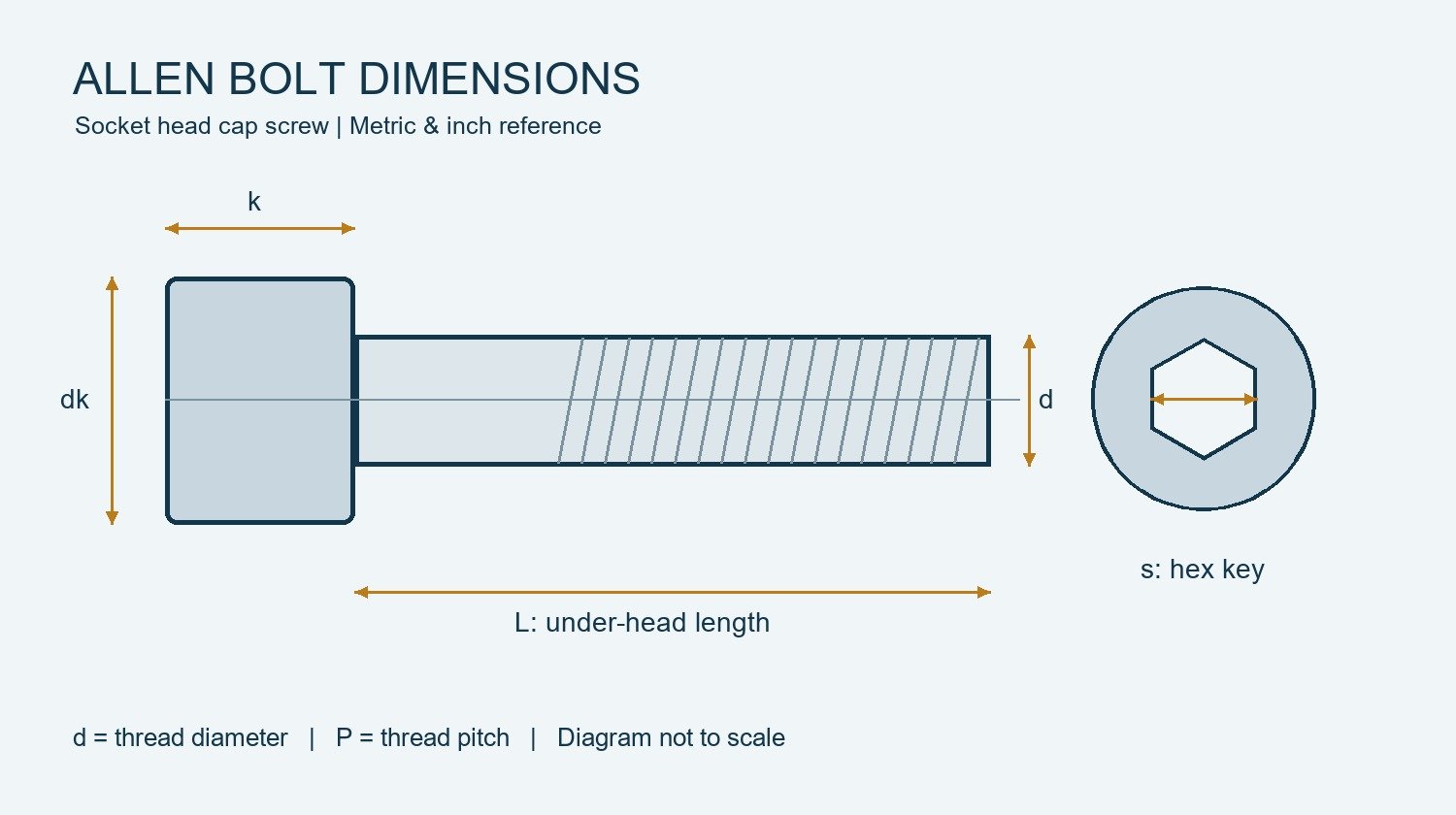
Start by cleaning the sample. Dirt inside the socket can stop a correct key from seating; a damaged thread can make an otherwise straightforward measurement misleading.
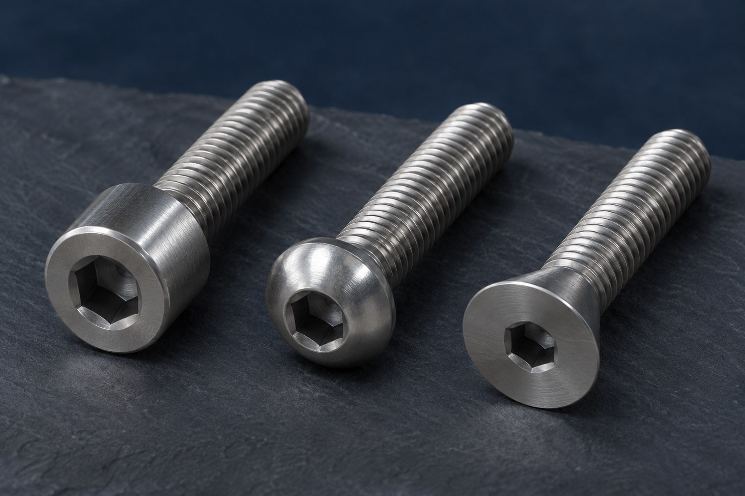
- Identify the head style. A tall cylindrical head, a domed button head and a conical flat head belong to different dimensional families.
- Measure the outside of the thread. Use calipers across the thread crests, rather than inside the hex socket. The measured value may sit slightly below the nominal diameter because of thread tolerances or wear.
- Check the pitch. Use a metric pitch gauge or an inch TPI gauge. Do not identify the thread by diameter alone.
- Measure the correct length. For a standard socket cap screw, measure from the bearing surface under the head to the end. For a conventional flat countersunk screw, nominal length includes the head.
- Check the key size and thread coverage. Seat an undamaged key fully, then record whether the screw is fully or partially threaded.
- Read the markings. Record the material or strength designation separately from dimensions. Appearance alone does not establish strength.
If a screw resists turning into a known mating thread by hand, stop and check it. Forcing a nearly matching metric or inch thread can damage both parts before the mismatch becomes obvious.
“Allen bolt” describes a drive, not one head shape
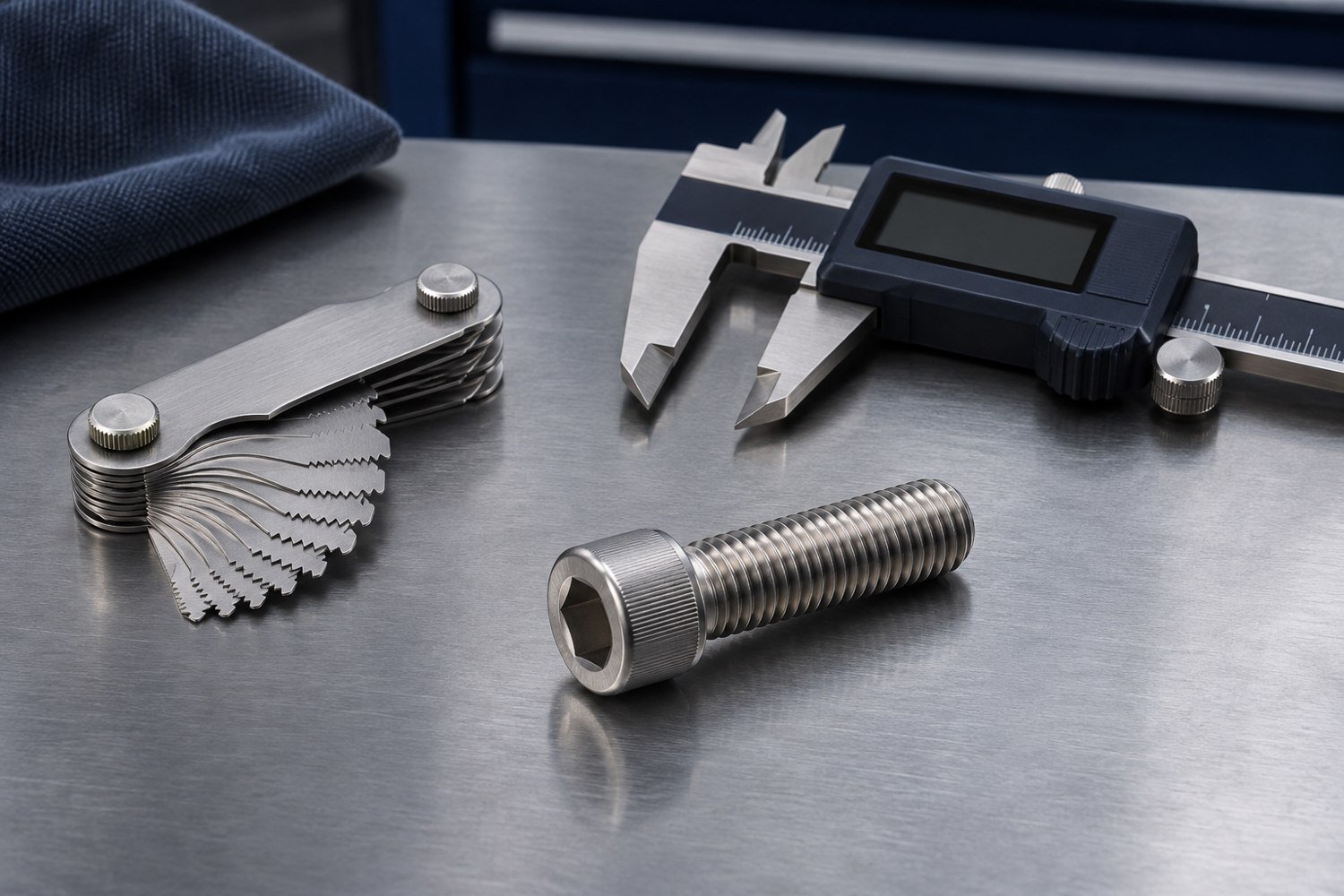
People often use Allen bolt, hex socket screw and socket screw interchangeably. That works in casual conversation, but it is not enough information for purchasing or machining a recess.
| Head or screw style | Common reference | Where it fits | Detail to confirm |
|---|---|---|---|
| Cylindrical socket head cap screw | ISO 4762; inch ASME B18.3 | Assemblies with room for the taller head or a counterbore | Head envelope, key access and under-head fillet |
| Button head | ISO 7380-1 for a common metric type | A low, rounded exposed head | Its own key size and loadability; do not reuse the cap-head chart |
| Flat countersunk head | ISO 10642 for a common metric type | A head seated in a matching conical recess | Countersink angle, seating diameter and overall length |
| Low head | DIN 7984 or a specified product design | Restricted height above the joint | Socket engagement and the product’s load limitations |
| Socket set screw | Standard depends on point form | Positioning or retaining a component without a conventional head | Point geometry, key size and contact conditions |
A shorter head is not a free substitution for a taller one. The head and socket geometry affect tool engagement and load capacity. Choose a replacement by its full specification, rather than by matching the thread and finding a key that fits.
Designing the clearance hole, tapped hole and counterbore
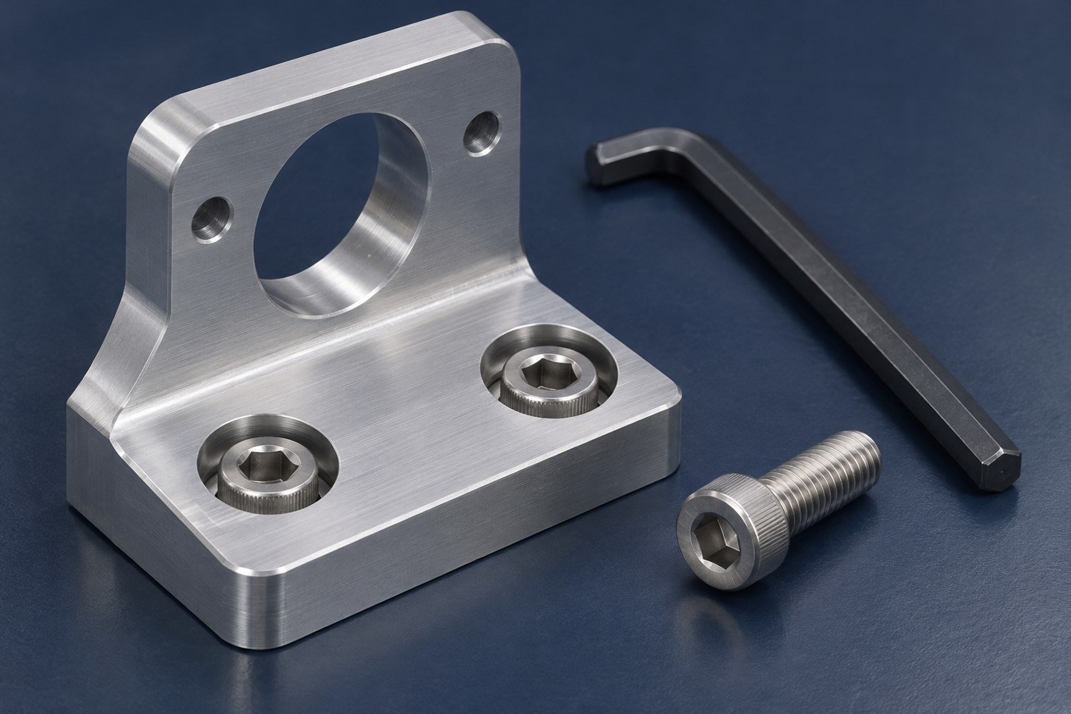
These three features do different jobs. A clearance hole lets the screw pass through the first component. A tapped hole provides the mating thread. A counterbore creates a flat-bottomed recess for the cylindrical head. Confusing them can leave an otherwise accurate part impossible to assemble.
| Feature | What determines its size? | Common mistake |
|---|---|---|
| Clearance hole | Screw diameter, required clearance series, positional tolerances and assembly method | Using the nominal screw diameter as the finished clearance-hole size |
| Tap-drill hole | Thread size, material, thread engagement and cutting versus forming tap | Treating a tap-drill estimate as the finished internal thread specification |
| Counterbore diameter | Maximum actual head envelope plus assembly and tool clearance | Making the recess exactly equal to the chart’s plain-head diameter |
| Counterbore depth | Head height, desired recess, washer if present and remaining wall thickness | Reducing the remaining material without checking the joint load path |
| Blind tapped-hole depth | Required usable thread, drill point, tap lead and screw-end clearance | Allowing the screw to bottom out before the parts clamp together |
A practical length calculation
Suppose a standard cap screw passes through a 6 mm plate and a 1.6 mm washer, then needs 12 mm of usable engagement in the mating part. The geometric total is 6 + 1.6 + 12 = 19.6 mm. A nominal 20 mm screw is a candidate, but it is not yet an approved selection: confirm the tolerance stack, usable thread depth, screw-end clearance and any unthreaded shank.
The 12 mm engagement in this example is an assumed design requirement, not a universal rule. The necessary engagement depends on the fastener, internal-thread material and joint load. Aluminum housings and steel blocks may need different solutions even when they use the same screw.
Coordinate fasteners with the machined part drawing
Call out the thread and recess independently. Specify the required internal thread tolerance, depth of usable thread, counterbore diameter and depth, and any positional requirement. If the part will be coated or anodized, identify how that finish affects the thread and seating surfaces.
For an assembly containing several similar screws, a short fastener schedule is worthwhile. It prevents an M6 button head from being substituted into a counterbore designed for a cylindrical cap head and makes inspection more straightforward.
Why a size chart is not a universal torque chart
Two screws with the same dimensions can require different installation torque. Strength class, coating, lubricant, mating material, thread engagement and the required clamp load all influence the result. A dry assembly value should not be reused automatically after adding oil or anti-seize.
A simplified relationship, T ≈ K × F × d, is useful for explaining the sensitivity. T is torque in N·m, F is preload in newtons, d is nominal diameter in meters, and K is an empirical nut factor representing friction-related effects. It is not a substitute for an approved tightening specification.
| Illustrative M8 calculation | Assumed preload F | Assumed K | Calculated T |
|---|---|---|---|
| Case A | 10,000 N | 0.15 | 12 N·m |
| Case B | 10,000 N | 0.20 | 16 N·m |
| Case C | 10,000 N | 0.25 | 20 N·m |
These are arithmetic examples, not recommended tightening torques. The same assumed preload gives different torque values as K changes. For production, use a specification validated for the actual fastener and joint, including the defined lubrication condition and tightening method.
What to include when ordering
“M8 Allen bolt” leaves several important choices unanswered. A useful purchasing description includes the head standard, thread diameter and pitch, length, material or strength class, finish, thread coverage and quantity. If traceability or inspection documents matter, request them at quotation rather than after delivery.
Standard hardware is generally the simplest starting point. A custom screw should solve a defined problem, such as an unusual shoulder, special length, restricted envelope or assembly feature. If a nonstandard component is needed, provide a drawing rather than asking a supplier to infer the design from a sample alone.
Frequently asked questions
What size Allen key fits an M6 bolt?
A standard cylindrical M6 socket head cap screw uses a 5 mm key. Check the head style first; other M6 socket screws can use a different key.
What size Allen key fits an M8 socket head cap screw?
The standard cylindrical-head type uses a 6 mm key. M8 describes the nominal thread diameter, not the tool size.
Does bolt length include the head?
For a standard cylindrical socket head cap screw, no: length is measured from under the head. A conventional flat countersunk screw is measured over its overall length, including the head.
Can a metric key replace an inch key?
Use the correct tool system and size. A nearly matching key may appear to fit but can concentrate force at the socket corners and damage the drive.
Are DIN 912 and ISO 4762 identical?
They are closely related references for cylindrical socket head cap screws, but should not be treated as universally identical purchasing specifications. Confirm the applicable standard and product drawing, especially for thread series, dimensions and available lengths.
Are all Allen bolts high-strength alloy steel?
No. The hex socket describes the drive. Material and mechanical properties must be identified separately from markings, documentation and the ordered specification.
Can I design a counterbore from the table alone?
The table is a starting point. Check the actual head envelope, clearance, recess depth, fillet and remaining material before releasing the part drawing.
Designing machined parts around socket screws?
Send MileMetal the component drawing and mating-fastener specification. Include tapped holes, counterbores, finishes and critical assembly dimensions so the enquiry can be reviewed as a complete part.
Related reading: Precision machined parts guide · OEM CNC machining enquiries