Outsourcing Custom Metal Parts: A Practical Guide to Machining Services
2026-10-28
Allen Bolt Size Chart: Metric & Inch Socket Head Cap Screw Dimensions
2026-11-09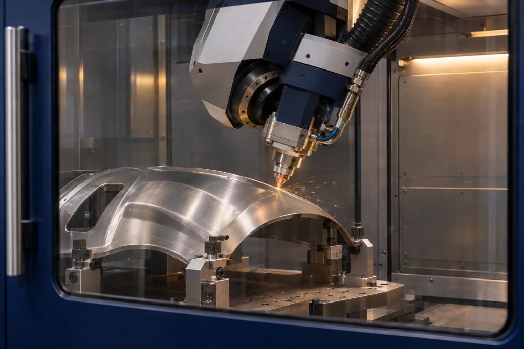
MILEMETAL · METAL MANUFACTURING INSIGHTS
3D Laser Cutting for Metal Parts: Process, Parameters & Design Guide
A hole in a flat sheet is straightforward. The same hole on the sloping wall of a formed housing brings a different set of questions: how to hold the part, reach the surface and keep the finished opening in the right position.
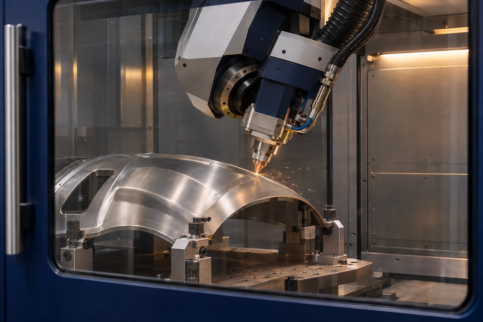
That is where 3D laser cutting becomes useful. It follows metal geometry beyond a single flat plane, making it possible to trim formed shells, prepare tube joints and add openings after bending or forming. The biggest benefit is often a simpler manufacturing route—not merely a faster cut.
In this guide: How it works · Process comparison · Materials · Parameters and calculations · Design and quality · Video · Cost and sourcing
What is 3D laser cutting?
In metal cutting, a focused beam heats a small region while an assist-gas jet helps remove molten material through the cut. The resulting gap is called the kerf. A programmed motion system carries the cutting point along the required contour.
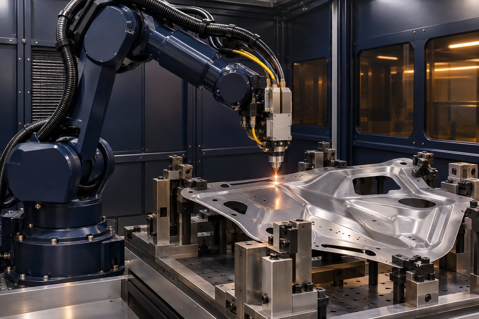
A flat-bed machine typically processes a sheet in one plane. A 3D system also changes the relative orientation of the head and workpiece so the nozzle can approach differently oriented surfaces. Depending on the equipment, this may involve a five-axis machine, an articulated robot, or a tube-processing system with rotary motion. These architectures overlap in application but are not interchangeable.
Three-dimensional cutting does not mean the beam can reach every surface inside a part. Deep recesses, hidden walls and tight internal corners may block the head or the escaping melt. Accessibility must be checked against the real nozzle, fixture and motion envelope—not just against a line drawn in CAD.
Where the process fits in production
Consider a formed metal enclosure with mounting holes on three angled faces. Cutting all openings before forming may be economical, but their final positions depend on bending and springback. Cutting selected features afterward allows them to be located from the formed component’s assembly datums. It adds a fixture and a cutting operation, so the improvement needs to justify the extra handling.
Tube work follows a similar logic. Holes, slots and shaped ends can be combined in a programmed operation, reducing separate sawing and drilling setups. A round tube with a saddle-shaped end can fit a mating tube more closely before welding, provided the joint allowance and angular orientation are correctly defined.

3D laser cutting, flat-sheet cutting or CNC machining?
Start with the finished geometry rather than a preferred machine. A part that can be cut flat and bent reliably may not need 3D cutting. Conversely, trying to mill every opening in a thin, curved shell may introduce unnecessary workholding and tool-access problems.
| Process | Strongest fit | What to check | Likely follow-up work |
|---|---|---|---|
| 2D laser cutting | Flat blanks, plates and profiles | Whether forming will move or distort critical features | Bending, deburring, tapping or finishing |
| 3D laser trimming | Accessible edges and openings on formed parts | Surface location, nozzle clearance and stable fixturing | Edge conditioning and selected precision machining |
| Tube laser cutting | Tube slots, holes, notches and joint profiles | Chuck range, tube seam, straightness and far-wall protection | Welding preparation, deburring and assembly |
| CNC milling or drilling | Pockets, threads, controlled bores and sealing faces | Tool access, rigidity and machining allowance | Surface finishing or assembly |
| Stamping with trim/pierce tooling | Stable designs at quantities that justify tooling | Tooling cost, design maturity and material behavior | Deburring, secondary machining or coating |
Hybrid routes are common. Laser cutting can create the overall opening while a later machining operation establishes a bearing seat, thread or close-fitting hole. Reserve the more demanding process for the features that actually require it.
From CAD model to a repeatable cut
- Review the formed model and drawing. Identify the material, local thickness, revision, assembly datums and features that must be produced after forming.
- Plan access and holding. Position supports away from the beam path and keep clamps clear of head movements. Decide where scrap will fall.
- Program and simulate. Establish approach paths, lead-ins, cut direction and head orientation. Include the fixture and machine geometry in collision checks.
- Prove the setup. Confirm part location and use controlled trials to establish a cut recipe for the actual material condition.
- Cut and manage heat. Sequence features to maintain support and limit local heat accumulation. Check small holes and interrupted contours separately.
- Finish and inspect. Remove loose dross, condition specified edges and measure the finished part from its agreed datums.
A successful first sample is only the beginning. Incoming formed parts must also sit consistently in the fixture. If springback changes from batch to batch, a fixed toolpath may produce different feature locations even when the cutting machine repeats perfectly.

Material choice and assist gas
State the alloy grade and delivery condition, not simply “steel” or “aluminum.” Coatings, protective film, surface contamination and local thickness changes can affect the process. A recipe proved on a flat coupon should be checked again on the actual formed geometry.
| Material family | Typical part examples | Process discussion | Inspection priority |
|---|---|---|---|
| Carbon steel | Brackets, structural tubes, formed panels | Oxygen-assisted cutting creates an oxidized edge; nitrogen may be considered where a cleaner edge is required | Dross, oxide removal before subsequent operations, feature location |
| Stainless steel | Housings, guards, process-equipment tubes | Nitrogen is commonly selected to limit edge oxidation; purity and delivery conditions matter | Edge discoloration, burrs and downstream surface requirements |
| Aluminum alloys | Lightweight enclosures and formed covers | Review equipment suitability, reflectivity, heat flow and melt removal | Edge roughness, local deformation and cosmetic finish |
| Coated or galvanized steel | Equipment covers and duct components | Confirm coating compatibility, extraction and the condition needed at the cut edge | Coating damage and corrosion protection at exposed edges |
| Titanium or specialized alloys | Application-specific formed components | Require a qualified material-specific route and agreed contamination controls | Metallurgical and functional acceptance criteria specified by the buyer |
Gas pressure should not be copied from an unrelated machine. Nozzle diameter, material thickness, power, focal position and the delivery system all affect the result. Oxygen and nitrogen also have different roles: oxygen contributes reaction heat, while nitrogen primarily supports melt removal and limits oxidation. Neither gas automatically guarantees a ready-to-weld or ready-to-coat surface.
The parameters that belong in a technical discussion
A useful parameter sheet connects each setting to a measurable result. Asking only for laser power leaves out much of the information that determines whether your part can be made reliably.
| Parameter | Unit | Why it matters | What to request |
|---|---|---|---|
| Local material thickness | mm | Affects energy input and melt removal; formed corners may differ from nominal stock | Minimum/maximum thickness where the cut travels |
| Laser power | W or kW | One part of the process window, not a standalone capacity guarantee | Qualified combination of grade, thickness and edge requirement |
| Cutting feed | mm/min or m/min | Actual feed falls around small features and difficult changes in orientation | Cycle-time estimate including pierces and non-cutting moves |
| Focus and nozzle standoff | mm | Influence energy distribution and gas delivery | Control method and accommodation of formed-part variation |
| Gas pressure and purity | bar; % or ppm | Influence melt ejection and edge chemistry | Validated recipe and supply requirements |
| Kerf width | mm | Affects contour compensation and small details | Measured result on representative geometry |
| Bevel angle | degrees | Changes access, effective cut length and joining geometry | Angle definition, tolerance and root-face requirement |
| Finished geometry | mm; degrees | Determines assembly fit | Drawing-based profile, position and angular acceptance criteria |
Numerical examples: what the figures actually tell you
The examples below are calculations using stated assumptions. They are not operating recipes, quoted prices or MileMetal machine specifications.
| Question | Example inputs | Calculation | Practical meaning |
|---|---|---|---|
| How long is the beam-on travel? | 1,200 mm contour at a constant 3,000 mm/min | 1,200 ÷ 3,000 × 60 = 24 s | Excludes acceleration, piercing, repositioning, loading and inspection |
| How does a bevel change the path through metal? | 3.0 mm wall; beam 45° from the surface normal | 3.0 ÷ cos 45° = 4.24 mm | About 41% longer geometric path; this is not a direct speed or power multiplier |
| What does kerf compensation mean? | Measured kerf 0.20 mm | Half-width = 0.10 mm | Nominal contour offset depends on inside/outside cut and calibrated CAM strategy |
| How does setup affect unit cost? | Illustrative setup/programming charge $180 | 20 pieces: $9.00 each; 200 pieces: $0.90 each | Only the allocated setup cost; material, processing, finishing and freight remain separate |
| What does a bilateral tolerance allow? | Drawing dimension 50.00 ±0.20 mm | Acceptable interval: 49.80–50.20 mm | The inspection setup and measurement uncertainty must suit that requirement |
These distinctions help avoid an expensive misunderstanding. A machine’s maximum traverse speed is not its sustained cutting feed, and its positioning accuracy is not a promise about the location of a hole in a flexible formed panel.
Design details that save time after the quotation
Locate features from how the part assembles
Choose datums that the fixture and inspection equipment can reproduce. An easy-to-touch flange may be convenient, but it is a poor reference if the assembly locates from a different face. For flexible parts, define whether measurements apply in the free state or in an agreed restrained condition.
Give the head—and the scrap—a clear route
Leave clearance around clamps, tall walls and neighboring features. A beam path that looks open in a CAD section may still be inaccessible to the nozzle body. On hollow sections, account for the opposite wall and internal spatter. Cutouts should not tip into the head path or remain trapped inside a closed part.
Specify edge condition where it affects function
“Burr-free” is often too vague. Identify handling edges, sealing interfaces and weld-preparation faces separately. If an edge radius, chamfer or burr-height limit matters, put it on the drawing and agree how it will be checked. Do not assume a thermal cut has the same surface condition as a milled face.
Keep precision machining where it earns its cost
Threads, fitted bores and seal-contact surfaces often need subsequent machining. Where an opening will be finish-machined, define the stock allowance with the supplier instead of specifying the final fit on the laser-cut edge. This keeps the route practical while protecting the important dimensions.

Quality checks: measure the part you intend to assemble
Inspect more than the visible cut line. Check feature position, profile, angular relationships, distortion and the condition of areas affected by cutting. First-article inspection should use representative production material and the intended fixture.
| Quality concern | Possible contributor | Useful verification |
|---|---|---|
| Hole location changes between parts | Incoming form variation, inconsistent seating or datum selection | Compare incoming geometry and clamped location before altering the toolpath |
| Dross or incomplete separation | Unstable cutting window, nozzle condition or gas delivery | Inspect representative edges and review the validated process settings |
| Distortion after release | Residual stress, heat input or over-restraint | Compare restrained and free-state measurements against the drawing requirement |
| Bevel differs along a contour | Head orientation, geometry variation or access limitations | Measure angle and root face at agreed locations |
| Damage inside a tube | Beam interaction or spatter on the far wall | Internal visual inspection or other agreed access method |
For repeat orders, retain the approved drawing revision, fixture references, program revision and inspection results. These records are more useful than a generic statement that a machine is “high precision.” They allow a later batch to be compared with the part that was actually approved.

Watch the supplied laser-cutting video
Use the player below to view the linked YouTube Short. A short production clip can help visualize movement and access, but it does not establish the material grade, dimensional accuracy or cycle time of a quoted part.
What drives the cost of 3D laser-cut parts?
Programming and fixtures can dominate a small order. As quantity increases, handling, cut length, piercing count, gas consumption and finishing become more important. A long simple contour may be quicker to process than a shorter path containing many small holes and changes of direction.
Ask for a quotation that separates one-time costs from repeat production. Include the cost of secondary operations and the usable yield, not just the price of cutting. Eliminating a drilling setup may justify a more expensive laser operation; requiring extensive edge repair afterward may reverse the saving.
When comparing suppliers, keep the scope identical: material source, supplied form, inspection, finishing, packaging and delivery terms. A quote for cutting customer-supplied formed blanks is not comparable with a quote that includes blanking, forming and final finishing.
Send a quotation package that can be assessed
- A STEP model of the finished geometry, plus a dimensioned PDF drawing with a revision identifier.
- Material grade, thickness and the condition in which the part enters cutting.
- Prototype quantity, batch quantity and anticipated repeat demand.
- Critical datums, tolerances, edge requirements and surfaces that need protection.
- Required forming, welding, machining, coating and inspection operations.
- Any sample-approval, traceability, packaging or delivery requirements.
For assemblies that combine formed parts and machined components, review the whole route early. Our OEM manufacturing page outlines drawing-based enquiries involving CNC machining, sheet metal and stamping. The suitable process route and any specialist processing arrangements should be confirmed for each project.
Frequently asked questions
Is 3D laser cutting the same as 3D printing?
No. Laser cutting removes material along a contour. Additive manufacturing builds material to create a part. A three-dimensional cutting path does not make the process additive.
Does every 3D laser machine have six axes?
No. Five-axis machines, articulated robots and rotary tube systems use different motion arrangements. The useful question is whether a particular system can reach and control your required contours.
How thick can the metal be?
There is no single thickness limit for 3D cutting. Material, power, cut angle, gas delivery and required edge quality all matter. Ask for a proven range for the exact grade and geometry rather than a maximum flat-sheet specification.
What tolerance should I put on the drawing?
Start with the assembly requirement. Discuss feasibility for the formed part, including its datums and restraint conditions. A blanket tight tolerance can add cost without improving function; critical interfaces may be better finished by machining.
Can holes be cut after bending or forming?
Yes, when the head can reach the surface and the part can be located reliably. This can help establish features from the final form, but access, springback and fixture cost still need review.
Will the cut edge need finishing?
It may. The answer depends on burrs, oxidation, appearance and downstream assembly. Welding, coating, sealing and hand-contact edges can each require a different acceptance condition.
Can the process replace CNC machining?
It can replace some contouring and hole-making operations. It does not generally replace machining for threads, controlled-depth pockets, sealing faces or precision bores. Combining the processes is often the more practical choice.
Discuss the right route for your metal part
Send MileMetal your drawings, material, quantities and critical assembly requirements. We can review the enquiry around the complete component and confirm the proposed manufacturing scope before quotation.