Type III Anodizing: Hardcoat Thickness, Tolerances & Design Guide
2026-10-22
CNC Machining for AI Server Liquid Cooling: A Component Design & Sourcing Guide
2026-10-23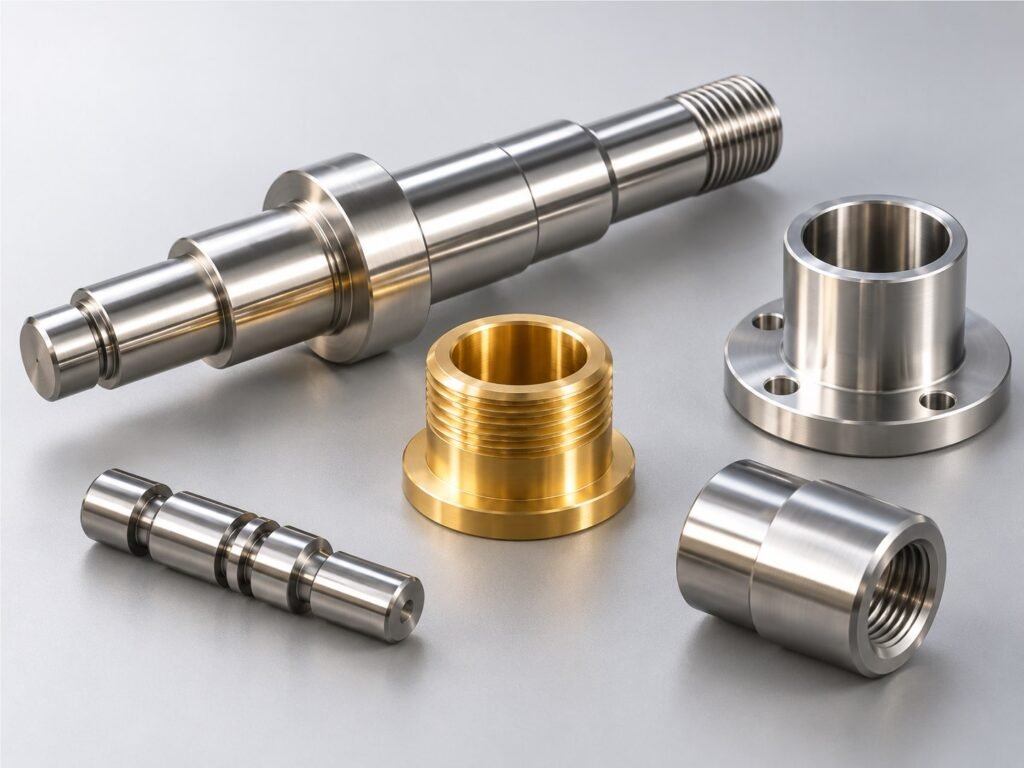
MILEMETAL ENGINEERING GUIDE · CNC MACHINING
What Is CNC Turning? Process, Materials, Parameters & Design Guide
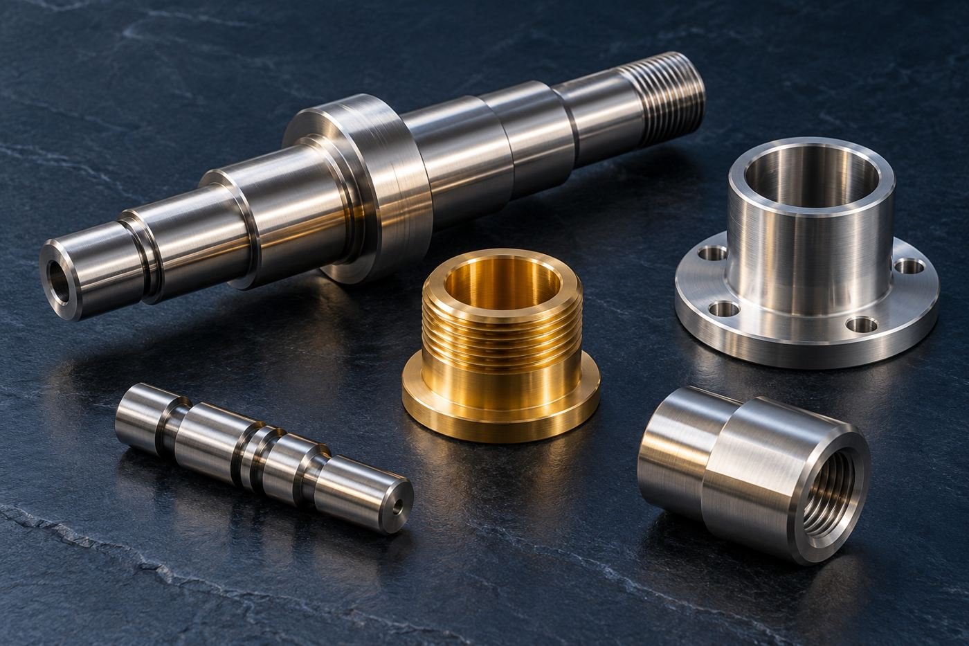
From a simple spacer to a threaded valve body, a successful turned part starts with the relationship between its centerline, mating surfaces and inspection requirements. This guide connects the machining process to the decisions that matter on your drawing and purchase order.
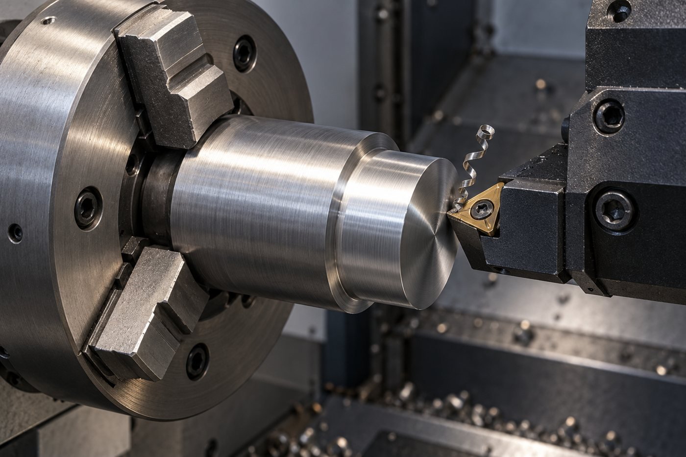
CNC turning removes material from a rotating workpiece with a computer-controlled cutting tool. It is particularly effective for diameters, faces, bores, grooves and threads that share an axis. A turning center with live tooling can also machine selected flats and cross-holes, depending on its configuration.
How does CNC turning work?
The spindle grips bar stock, tube or a prepared blank in a chuck or collet. During conventional turning, the workpiece rotates while a nonrotating tool moves along the programmed path. Z motion follows the spindle axis; X motion changes radial position. Many CNC lathe controls program X values as diameters, so a diameter change must not be confused with the physical radial movement of the tool.
A CAD model describes geometry, but it does not independently define a complete manufacturing process. Someone still needs to choose stock, tools, workholding, cutting data, operation order and inspection methods. CAM software or manual programming creates the toolpaths, and the setup must be checked before production.
- Review the drawing. Identify datums, mating diameters, surface requirements, threads and any dimensions that apply after finishing.
- Plan stock and clamping. Leave enough material for secure gripping and cleanup. Decide how the second end will be finished without damaging the first.
- Rough the geometry. Remove bulk material while leaving controlled finishing allowance and enough stiffness for subsequent operations.
- Finish functional features. Complete critical diameters, bores, faces, grooves and threads in a sequence that preserves their relationships.
- Complete secondary work. Add cross-holes, deburr intersections, apply specified treatments and inspect the finished condition.
For introductory process background, see Wevolver’s CNC turning overview. The planning examples and calculations below are developed for this guide.
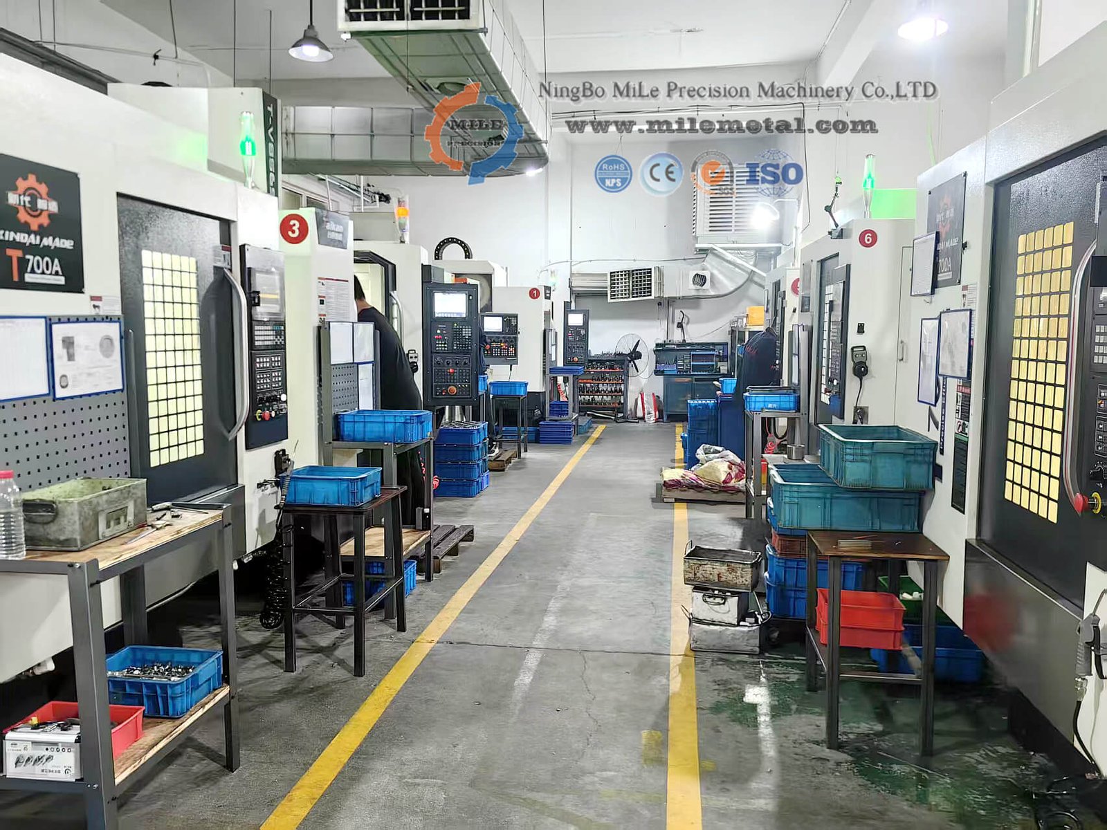

CNC turning operations and the features they create
A drawing may look like a single cylindrical component but require several tools. A deep bore, a sealing groove and a fine thread each introduce different access, chip-control and measurement needs.
| Operation | Result | Check before release |
|---|---|---|
| Facing | End face perpendicular to the turning axis | Overall length, face datum and edge break |
| OD / profile turning | Straight diameters, shoulders, tapers and radii | Fit, runout, shoulder access and blend radii |
| Drilling and boring | Axial hole followed by controlled internal geometry | Usable depth, bottom shape and boring-bar clearance |
| Reaming | Sizing and finishing a prepared hole | Pre-hole condition, allowance and required hole location |
| Grooving | Seal seats, retaining-ring grooves and reliefs | Width, depth, root radius and mating hardware |
| Thread turning | External or internal helical profile | Thread standard, pitch, class, hand and full thread length |
| Parting-off | Separation from bar stock | Back-face allowance, pip removal and part handling |
| Knurling | Grip or retention texture | Pattern, finished diameter and whether forming or cutting is intended |
Knurling deserves particular attention: forming knurls displace material and can increase the outside diameter. A drawing that only states the pre-knurl diameter may not control the final fit. Likewise, a drilled hole is not automatically a precision bore, and reaming does not reliably correct a substantially misplaced pre-hole.
CNC turning vs. milling: choose the process around the part
Start with the features that must relate accurately to one another. A shaft with multiple bearing seats naturally favors turning. A rectangular bracket with pockets favors milling. A round body with radial ports may justify a combined process.
| Route | Good starting point | Main planning consideration |
|---|---|---|
| Two-axis CNC turning | Coaxial sleeves, spacers, pins and simple shafts | Nonrotational features usually require another operation |
| Turning with live tooling | Round bodies with flats, slots or cross-holes | Tool access, C-axis control and available Y-axis travel vary |
| Swiss-type turning | Small, slender components needing support close to the cut | Bar quality, guide-bushing arrangement and setup economics |
| CNC milling | Prismatic parts, pockets and features distributed across faces | Fixture access and setup changes |
| Turning plus grinding | Selected hardened or demanding bearing and sealing surfaces | Grinding allowance, heat-treatment distortion and final inspection |
A subspindle can transfer a part for back-end machining, but the transfer still needs controlled gripping and alignment. “One machine” does not mean “no setup error.” Specify the required relationship between features so the supplier can choose an appropriate route.
For longer, smaller parts, see our Swiss-type CNC machining design guide. HPPI’s turning knowledge base provides additional background on machine arrangements and workholding.
Materials for CNC turned parts
Choose the alloy for the component’s service environment first, then discuss machinability and supply condition. “Stainless steel” or “aluminum” alone leaves too many variables open for a dependable quote.
| Material family | Example grades | Why consider it? | What to define |
|---|---|---|---|
| Aluminum | 6061-T6, 7075-T6 | Low mass for housings, sleeves and adapters | Temper, corrosion environment and anodizing requirements |
| Stainless steel | 303, 304, 316L | Corrosion-resistant fittings and mechanical parts | Exact grade; machinability, welding and corrosion needs differ |
| Carbon / alloy steel | 1045, 4140 | Load-bearing shafts and wear-related components | Supply hardness, heat treatment and final surface condition |
| Brass | C36000 or specified lead-free alloy | Threaded fittings, inserts and connector bodies | Composition and any application-specific lead restrictions |
| Titanium | Ti-6Al-4V | Strength-to-weight and corrosion requirements | Material standard, stock condition and thermal control |
| Engineering plastics | POM, PA, PTFE | Low-mass spacers, bushings and electrical isolation | Moisture, temperature, creep and measurement conditions |
Do not substitute a free-machining grade simply because its name resembles the specified alloy. Mechanical performance, weldability and corrosion behavior can change. For plastics, a diameter measured immediately after machining may differ after temperature or moisture equilibration. Agree on the acceptance condition when fit is important.


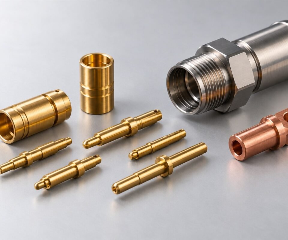
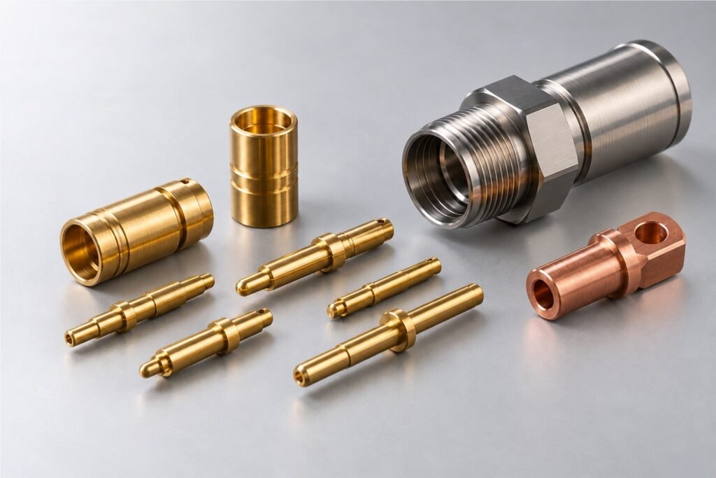
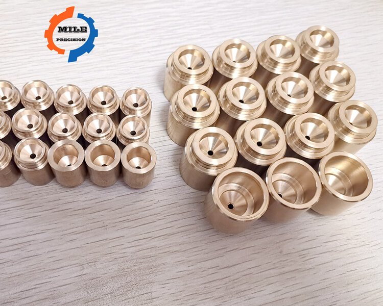
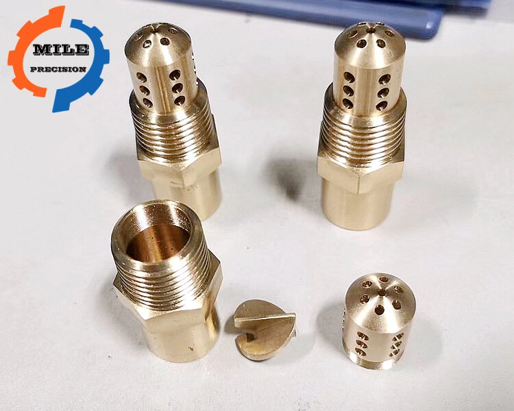
These library photographs illustrate component geometry; they do not establish the material grade or tolerance of a new order. Related applications include precision turned connector components.
CNC turning parameters: speed, feed and depth of cut
Cutting speed is the surface velocity at the cutting diameter. Spindle speed is revolutions per minute. Feed per revolution describes how far the tool advances during each revolution. Keeping these quantities separate makes a machining estimate easier to review.
| Symbol | Parameter | Unit | Example input |
|---|---|---|---|
| D | Cutting diameter | mm | 30 |
| vc | Cutting speed | m/min | 150 |
| n | Spindle speed | rev/min | Calculated below |
| f | Feed per revolution | mm/rev | 0.15 |
| ap | Radial depth of cut | mm | 1.0 |
| L | Engaged cutting length | mm | 60 |
n = 1,000 × vc / (π × D)
n = 1,000 × 150 / (π × 30) ≈ 1,592 rpm
Axial feed rate = f × n = 0.15 × 1,592 ≈ 239 mm/min
Ideal engaged cutting time = L / (f × n)
60 / 239 ≈ 0.251 min ≈ 15.1 seconds
The equations follow Sandvik Coromant’s metric turning formula reference. The numerical inputs are teaching examples, not recommended settings for a particular alloy or insert. Cutting data must come from the selected tool, material condition and actual setup.
The 15.1-second result covers one engaged straight pass at constant feed and speed. It excludes approach, retract, acceleration, tool changes, multiple passes, loading, inspection and secondary operations. It is therefore not a finished-part cycle time or quotation.
Three parameter mistakes to avoid
- Confusing radius and diameter. Turning an outside diameter from 32 mm to 30 mm removes 1 mm radially: ap = (32 − 30) / 2.
- Keeping RPM unchanged as diameter changes. At the same target cutting speed, a 15 mm diameter requires twice the RPM of a 30 mm diameter. Constant-surface-speed control must respect a suitable maximum spindle speed and workholding limits.
- Reducing feed without considering the insert. A very small chip load may cause rubbing or poor chip breaking. Surface quality also depends on edge condition, nose radius, rigidity and material behavior.
For facing, the cutting diameter decreases toward the center. The straight-pass estimate above does not model that changing geometry. For threading, the axial advance is tied to thread lead; ordinary turning-feed assumptions cannot be reused unchanged.
Design turned parts around function, access and stiffness
Define a usable datum strategy
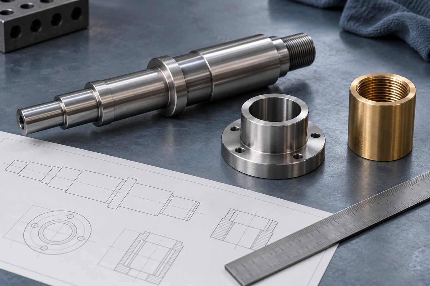
Consider a sleeve that locates on its bore and seats against an end face. Those functional surfaces are a useful starting point for the datum scheme. An arbitrary outer surface may be convenient to measure but irrelevant to assembly. Define the needed geometric control rather than asking for every diameter to be “concentric.” The applicable drawing standard determines the correct symbols and interpretation.
Keep thin walls and long overhangs under control
A slender shaft can deflect under cutting load. A thin sleeve can become round in the chuck and oval after release. Review unsupported length, clamping pressure and finishing sequence before tightening a tolerance. Tailstock support, a steady rest, a different fixture or a revised geometry may be more effective than adding another finish pass.
Give tools room to enter and leave
Internal corners inherit a tool-tip radius. Deep, narrow recesses restrict tool access and chip removal. Threads need a practical lead-in and an agreed runout or relief arrangement. Define usable full thread length separately from the total drilled depth, especially in blind holes.
| Feature | Example requirement | Engineering review |
|---|---|---|
| Nonmating length | 40.0 ±0.10 mm | Confirm that the assembly stack allows this variation |
| Mating diameter | Ø20.000 ±0.010 mm | Review fit, temperature, process capability and measurement uncertainty |
| Functional surface | Ra ≤1.6 µm | Identify the surface and agreed texture measurement conditions |
| External metric thread | M12 × 1.5–6g, 12 mm full thread | Confirm mating thread, lead-in, runout and gauging |
| Coated fit surface | Dimension applies after finishing | Allocate coating allowance and specify masking if needed |
How to use these numbers: they are hypothetical drawing examples, not default tolerances, universal design rules or a MileMetal capability guarantee. Final values require the mating-part design and supplier review. Ra is a texture parameter; it does not by itself control roundness, waviness or dimensional accuracy.
Finishing belongs in the initial process plan. Anodizing, plating and heat treatment can change the dimensions or condition of functional surfaces. For aluminum coating allowances, read our Type III anodizing design guide.
How to inspect CNC turned parts
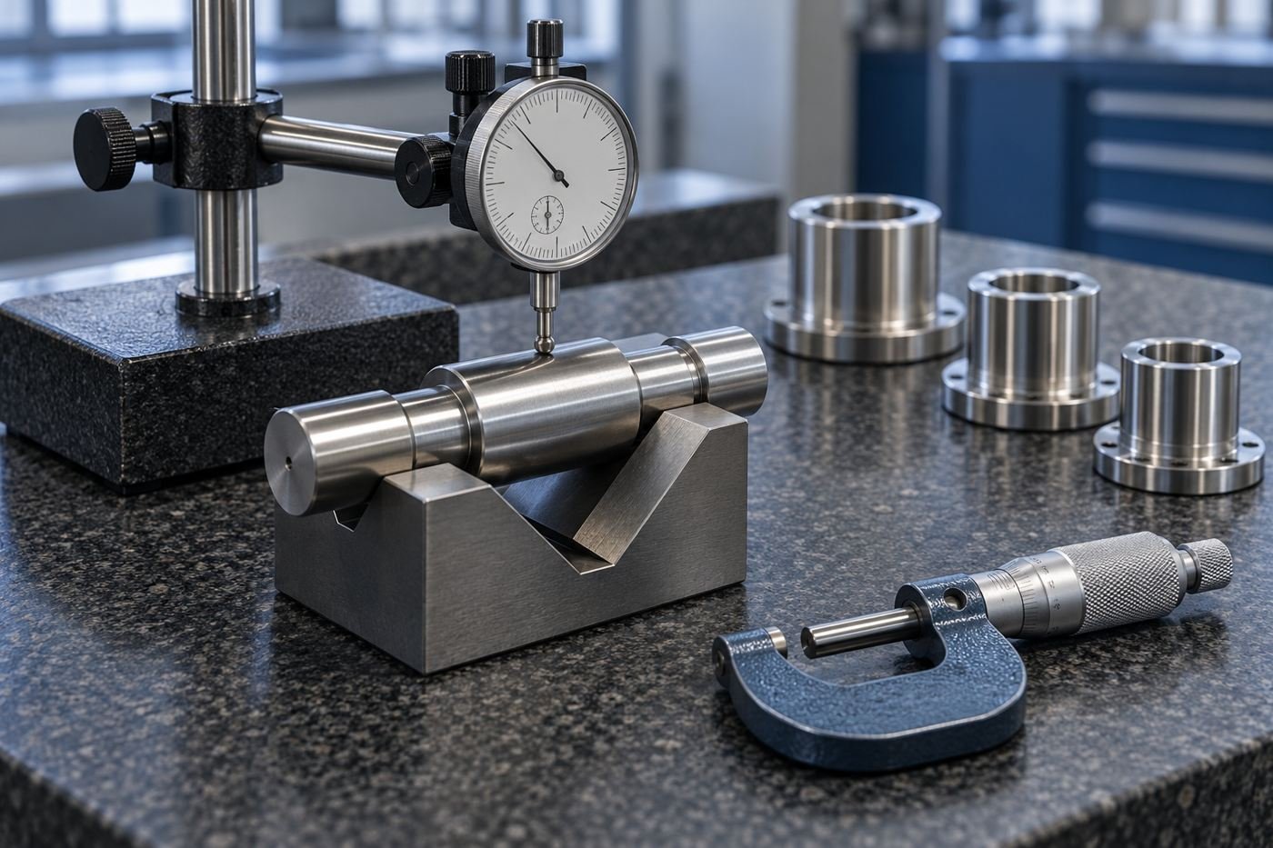
Inspection should follow the drawing’s functional requirements. Checking an outside diameter with a micrometer does not establish that the bore is aligned to it. A visually smooth surface does not demonstrate the specified roughness. Build the inspection plan around the feature, datum and acceptance limit.
| Requirement | Possible method | Important limitation |
|---|---|---|
| Outside diameter | Calibrated micrometer; multiple axial and angular locations | One reading can miss taper or local form variation |
| Bore diameter | Bore gauge, suitable internal instrument or air gauging | Access, calibration and depth affect the result |
| Thread acceptance | Appropriate GO / NO-GO gauges and specified checks | Pitch alone does not define thread acceptance |
| Runout relative to a datum | Controlled datum setup and indicator or suitable metrology system | The fixture must represent the specified datum |
| Surface texture | Profilometer with agreed evaluation settings | Trace direction and filtering affect reported values |
| Complex feature relationships | CMM or optical measurement where appropriate | Method, access and uncertainty must suit the tolerance |
For repeat orders, agree on first-piece approval, sampling or full inspection of selected features, and how tool wear is monitored. A dimension report is more useful when it identifies the drawing revision, feature number, nominal value, limits and measured result. Add material traceability and finish documentation where the application requires them.


Also check burrs where cross-holes meet internal bores. These intersections can be difficult to reach and may matter more to flow, sealing or assembly than the cosmetic appearance of the outside surface. Specify cleanliness and edge requirements in measurable terms where they are functional.
What affects CNC turning cost?
Unit cost combines material, setup, machining time, secondary work, inspection and expected yield. A short cycle is only one part of that total. For a small batch, programming and dedicated workholding may dominate. For a repeat production run, stable chip control, tool life and automated handling become more influential.
Useful cost reductions often come from relaxing a nonfunctional tolerance, standardizing thread sizes, allowing a tool-friendly relief or selecting stock closer to the final shape. Removing an inspection requirement without understanding its purpose can move cost downstream into assembly failures.
Send a quotation package that answers these questions
- Geometry: provide a 3D model plus a controlled 2D drawing with revision and units.
- Material: state alloy, temper or hardness, and required material documentation.
- Function: highlight critical fits, datum relationships, sealing areas and threads.
- Finish: define treatment, roughness, masking and whether dimensions apply before or after coating.
- Quantity: distinguish prototype quantity, first order and expected repeat demand.
- Acceptance: list required reports, sampling expectations, cleanliness and packaging.
- Delivery: provide the target schedule and any staged shipment needs.
See our CAD file format guide when preparing data. JLCCNC’s turning introduction also covers common materials and supplier-selection questions; this guide expands that overview into a practical drawing and RFQ workflow.
Planning a custom turned component?
Send MileMetal your drawing, material, quantity and critical requirements. Ask for a process review covering workholding, machining sequence, finishing allowances and inspection before finalizing the order.
Discuss your CNC turning projectExplore CNC turning services →
Frequently asked questions
Is CNC turning the same as a CNC lathe?
Turning is the process; a CNC lathe is a machine used to perform it. A turning center may add live tools, a subspindle and other functions. Machine names alone do not establish which features can be completed in one setup.
Can CNC turning produce square or asymmetric features?
Conventional turning creates surfaces about the spindle axis. Flats, cross-holes and slots require additional tool motion or another operation. Suitable live-tool turning centers can combine some of these features with turning.
What tolerance can CNC turning achieve?
There is no single tolerance for every part. Diameter, length, material, wall thickness, clamping, tool wear, finishing and inspection conditions all matter. Submit the functional tolerance for review rather than assuming a published machine resolution is a finished-part guarantee.
Is CNC turning economical for prototypes?
It can be, particularly when round stock and standard tools suit the geometry. Setup costs are spread across fewer pieces, so prototype unit prices can be substantially higher than repeat-production prices.
What is the difference between feed and cutting speed?
Cutting speed describes how fast the material surface passes the cutting edge, commonly in m/min. Feed describes tool advance, commonly in mm per workpiece revolution. Spindle RPM connects surface speed to cutting diameter.