
CNC Machining for AI Server Liquid Cooling: A Component Design & Sourcing Guide
2026-10-23
How Do You Choose an OEM Metal Parts Supplier?
2026-10-26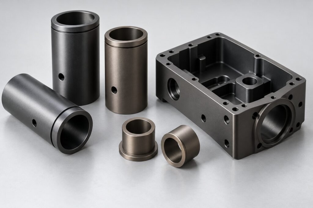
MILEMETAL · SURFACE FINISHING INSIGHTS
Hardcoat Anodizing + PTFE Impregnation: Process, Benefits & Design Guide
Hardcoat anodizing with PTFE treatment combines a wear-resistant aluminum oxide layer with a lubricious surface. For cylinders, guides, sleeves and other moving components, the useful question is how that finish will behave in the actual assembly—and how to specify it before machining begins.
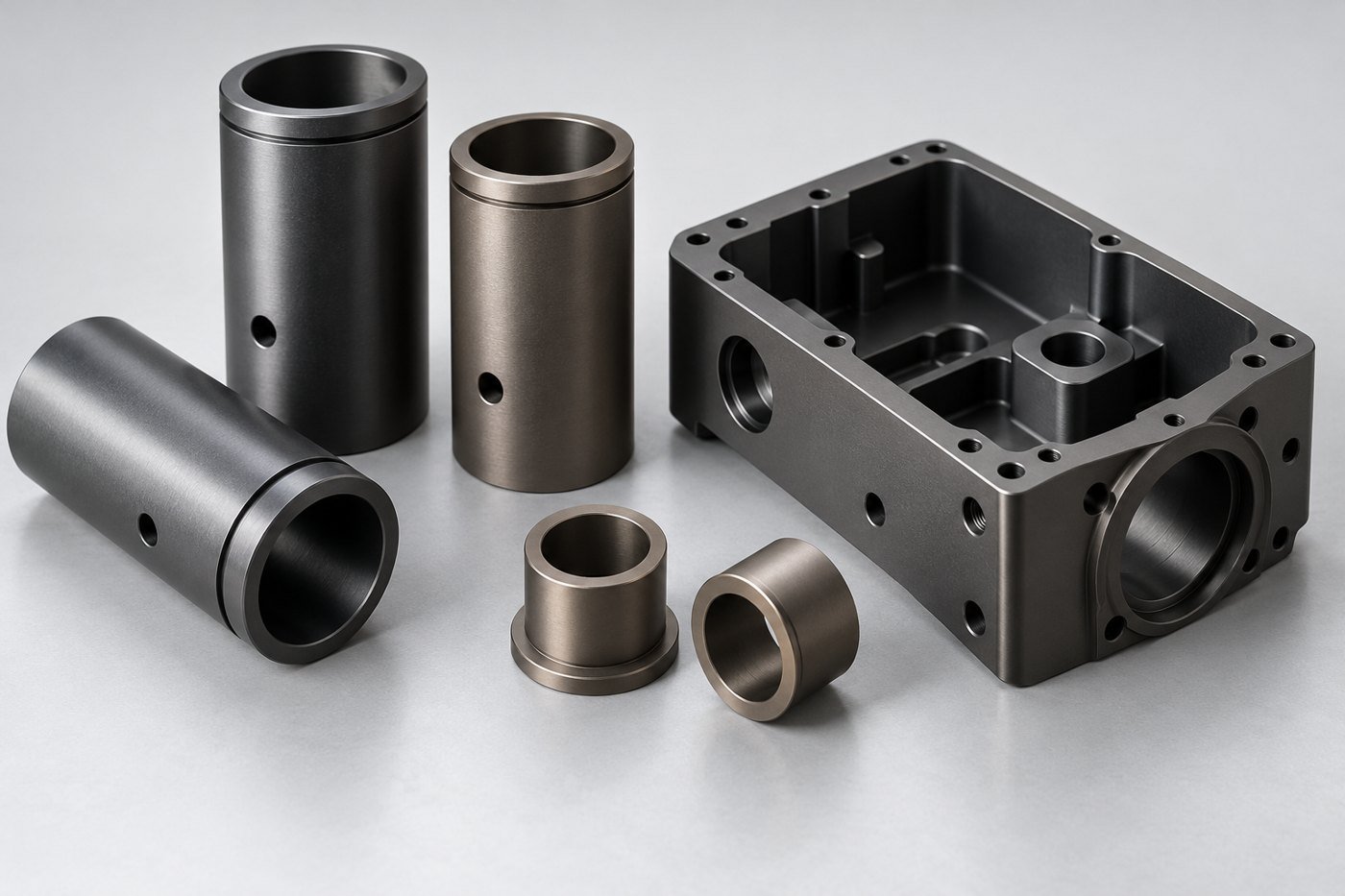
What is hardcoat anodizing with PTFE impregnation?
Hardcoat anodizing, often called Type III anodizing, converts the surface of an aluminum component into an aluminum oxide layer. PTFE—polytetrafluoroethylene—is then incorporated through a specified treatment to improve the behavior of the contact surface. The oxide and the polymer serve different purposes: the oxide supports wear resistance, while the PTFE-containing surface can reduce friction and sticking.
This combination is worth considering when a lightweight aluminum part needs more than a decorative finish. A guide that starts reluctantly, a sleeve that wears at a contact point or a surface that retains process material may benefit from a different surface system. The treatment still has to match the contact pressure, mating material, motion and environment.
NASA’s process specification describes PTFE-treated hard anodic coatings and emphasizes that coating properties vary between suppliers. Its practical implication is straightforward: identify the approved process, rather than assuming every finish sold as “hardcoat + PTFE” is interchangeable. Source: NASA PRC-5011, Rev. B.
What changes when PTFE is added?
Think of the finish as a contact system. The component surface is only one side of it; the counterface and operating conditions complete the picture. A low-friction result measured against one material under one load is not automatically the result in a different machine.
| Surface option | Main reason to consider it | What to resolve before ordering |
|---|---|---|
| Conventional Type II anodizing | Appearance and general surface protection | Color, thickness, sealing and the required service environment |
| Unsealed hardcoat | Abrasion resistance where the specified process calls for an unsealed finish | Wear requirements, corrosion exposure and handling of the surface |
| Conventionally sealed hardcoat | A finish selected with corrosion protection or dye retention in mind | Seal type and its effect on the required wear behavior |
| Hardcoat with a defined PTFE treatment | Wear resistance combined with improved sliding or release behavior | Exact process, friction test conditions, dimensions and acceptance criteria |
Anoplate distinguishes the wear and corrosion priorities of unsealed and sealed hardcoat and identifies PTFE treatment as a lubricity option. The choice should follow the application rather than a blanket instruction to seal every hardcoat surface. Hardcoat anodize technical overview.
A useful design review begins with the symptom you want to improve. Is the issue starting friction, steady sliding force, abrasive wear, adhesion of process material or corrosion at a joint? State that priority in the enquiry. It gives the coating discussion a direction and makes the later test meaningful.
The process: from machined part to finished interface
The sequence below is a planning guide, not a universal bath recipe. The selected processor controls chemistry, electrical conditions, treatment time and any curing or sealing stages through its approved procedure.
Review the drawing and intended service
Identify the alloy and temper, surfaces to be treated, finished fits, surface texture and required performance. Explain the mating material and movement. Separate a cosmetic preference from a functional requirement, and confirm the inspection records needed with the order.
Machine and prepare the component
Leave the agreed allowance on features that will change during finishing. Complete the required edge geometry and remove burrs. A coating should not be expected to correct a poor bore, an unwanted tool mark or an incorrect thread. Define which surface requirements apply before treatment and which apply afterward.
Plan masking and electrical contact
Mark threads, precision seats, grounding areas and other zones that must remain untreated. Agree on rack contact locations and acceptable witness marks. For a housing with several ports, a marked drawing is much clearer than “mask important holes.”
Clean, pretreat and hard anodize
The processor prepares the surface and grows the anodic oxide under controlled conditions. Coverage and access need particular attention in recesses and long bores. Treat the external surface and the internal working surface as separate inspection locations when the design depends on both.
Apply the specified PTFE treatment
Use the agreed process and its prescribed sequence. Some treatments have little additional dimensional build; other coating systems may introduce a distinct film. Confirm the actual system rather than substituting a generic fluoropolymer finish after the hardcoat has been produced.
Inspect, evaluate and protect
Check the finished dimensions, coating thickness and specified surface characteristics. Where friction or wear drives the design, evaluate representative parts or coupons under agreed conditions. Package finished contact surfaces so that they cannot rub against adjacent parts in transit.
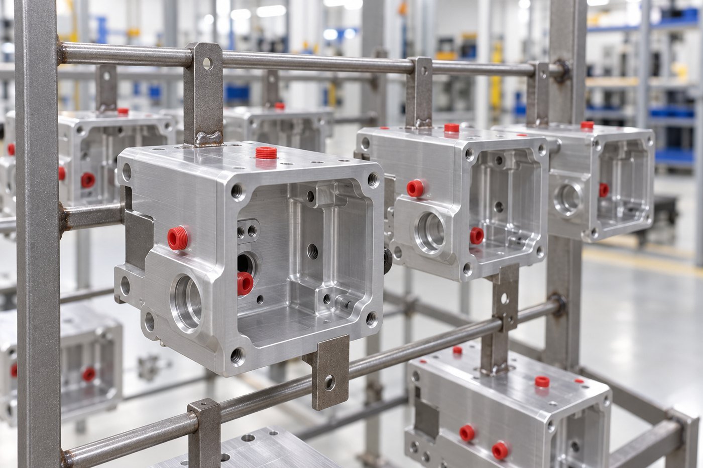
Production details that deserve attention
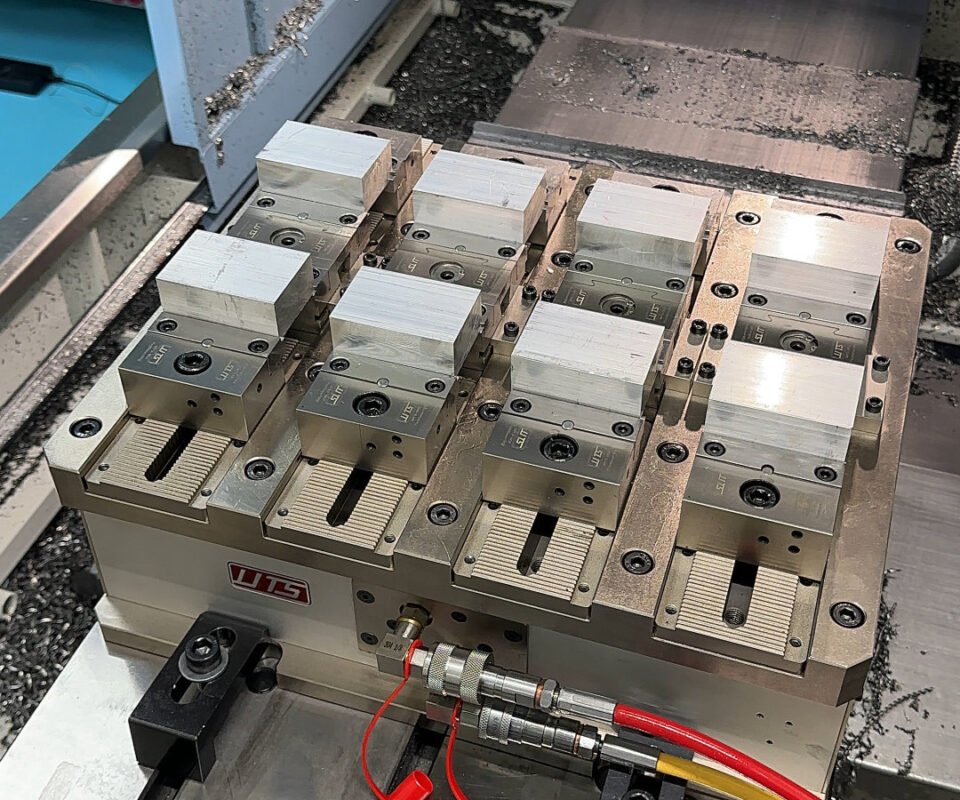
The photographs below were supplied for this article. They illustrate part geometry, masking, racking and handling considerations. Appearance alone does not verify alloy, coating chemistry, PTFE content or a test result.
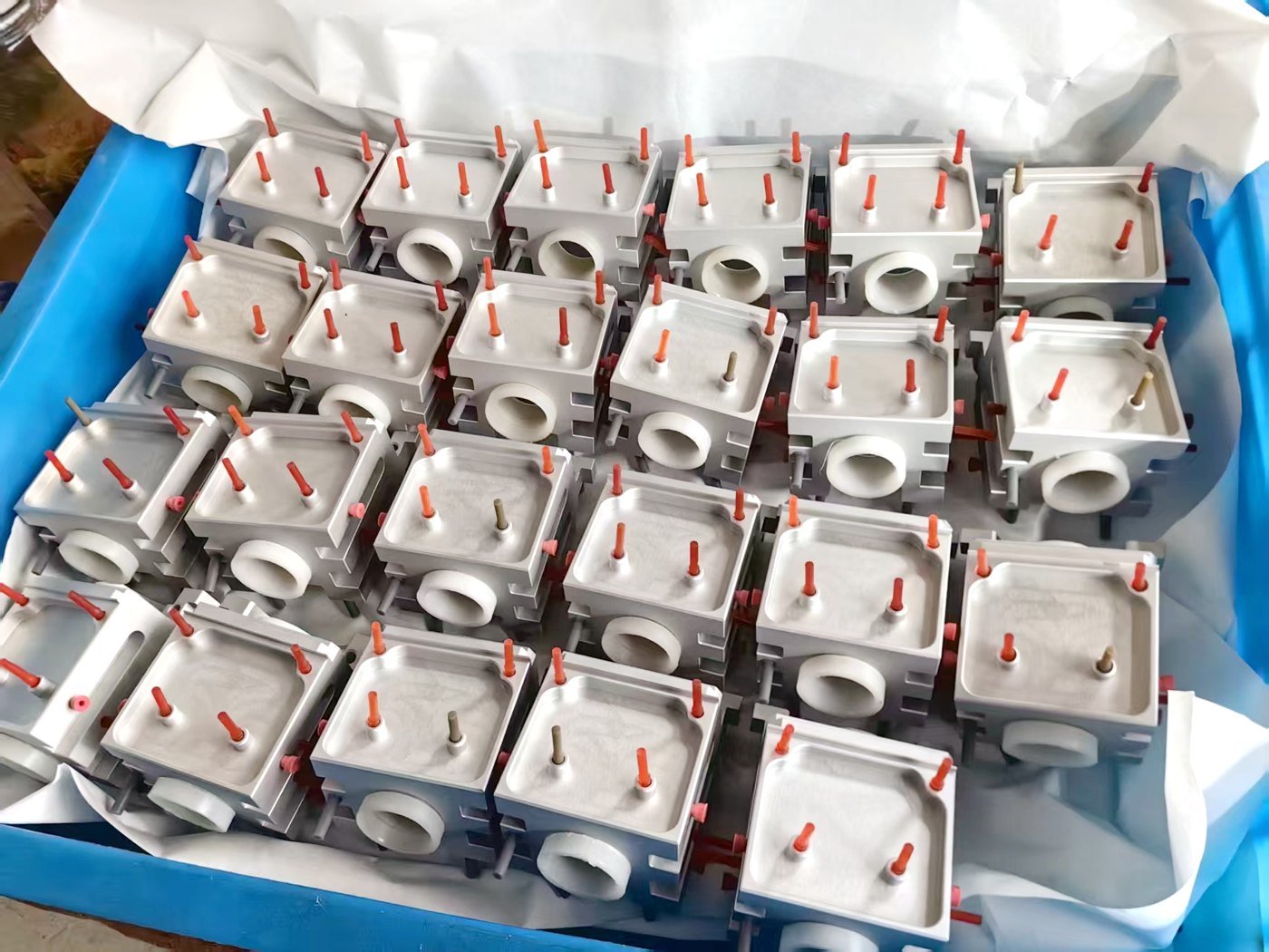
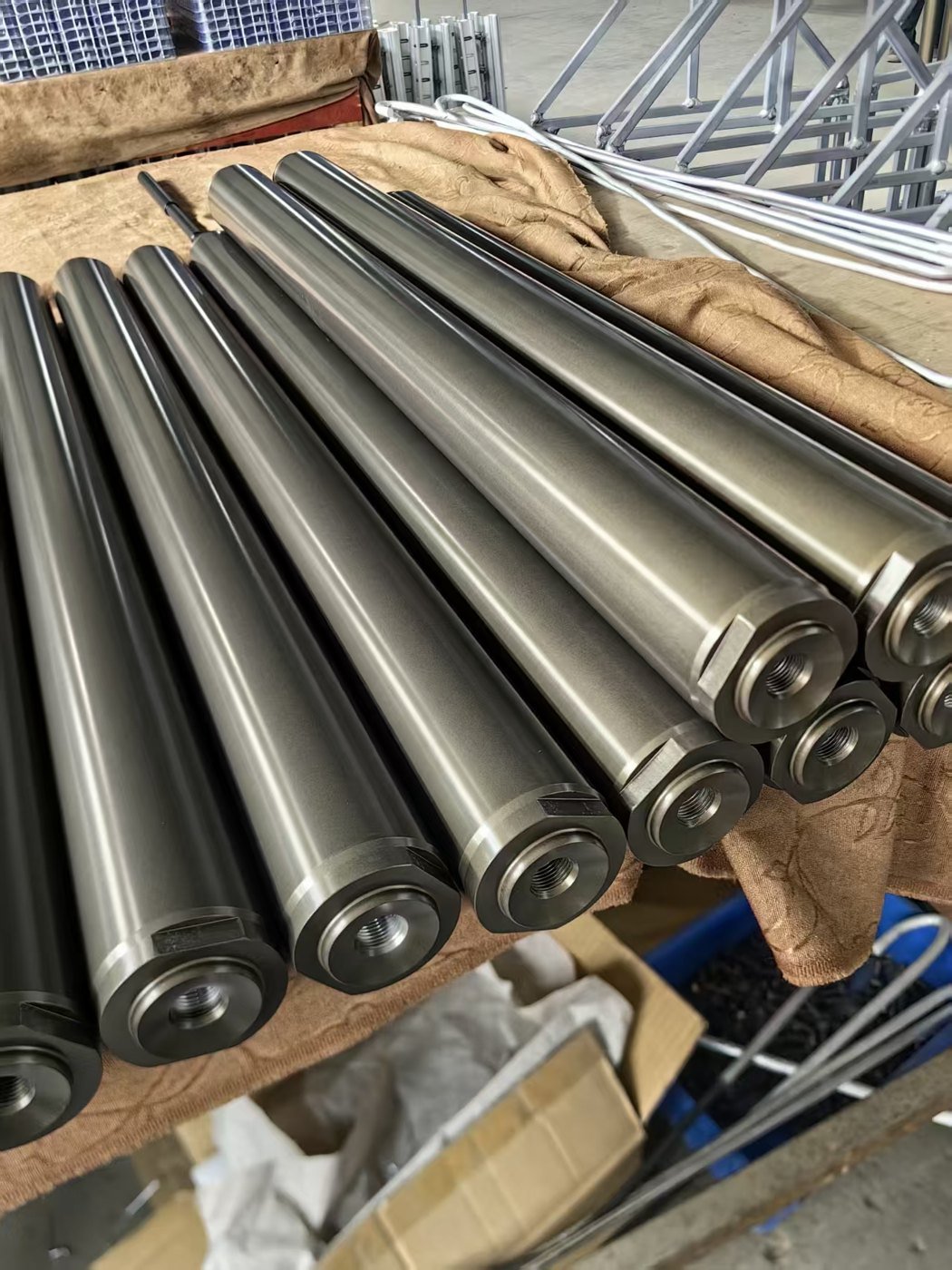
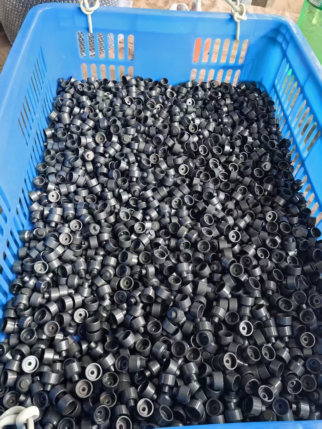
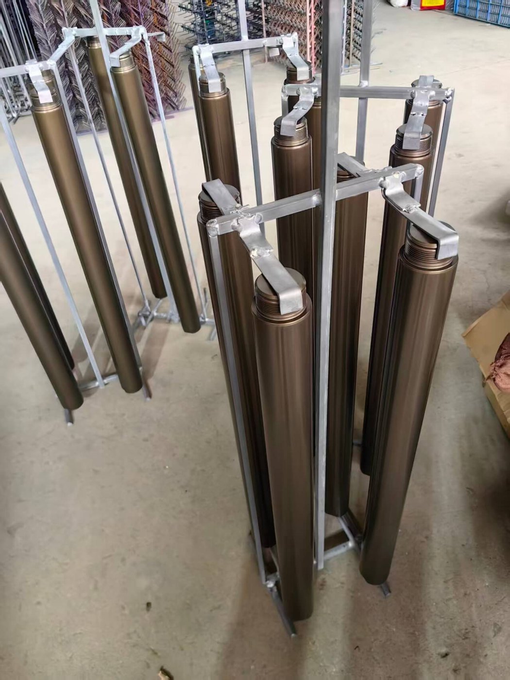
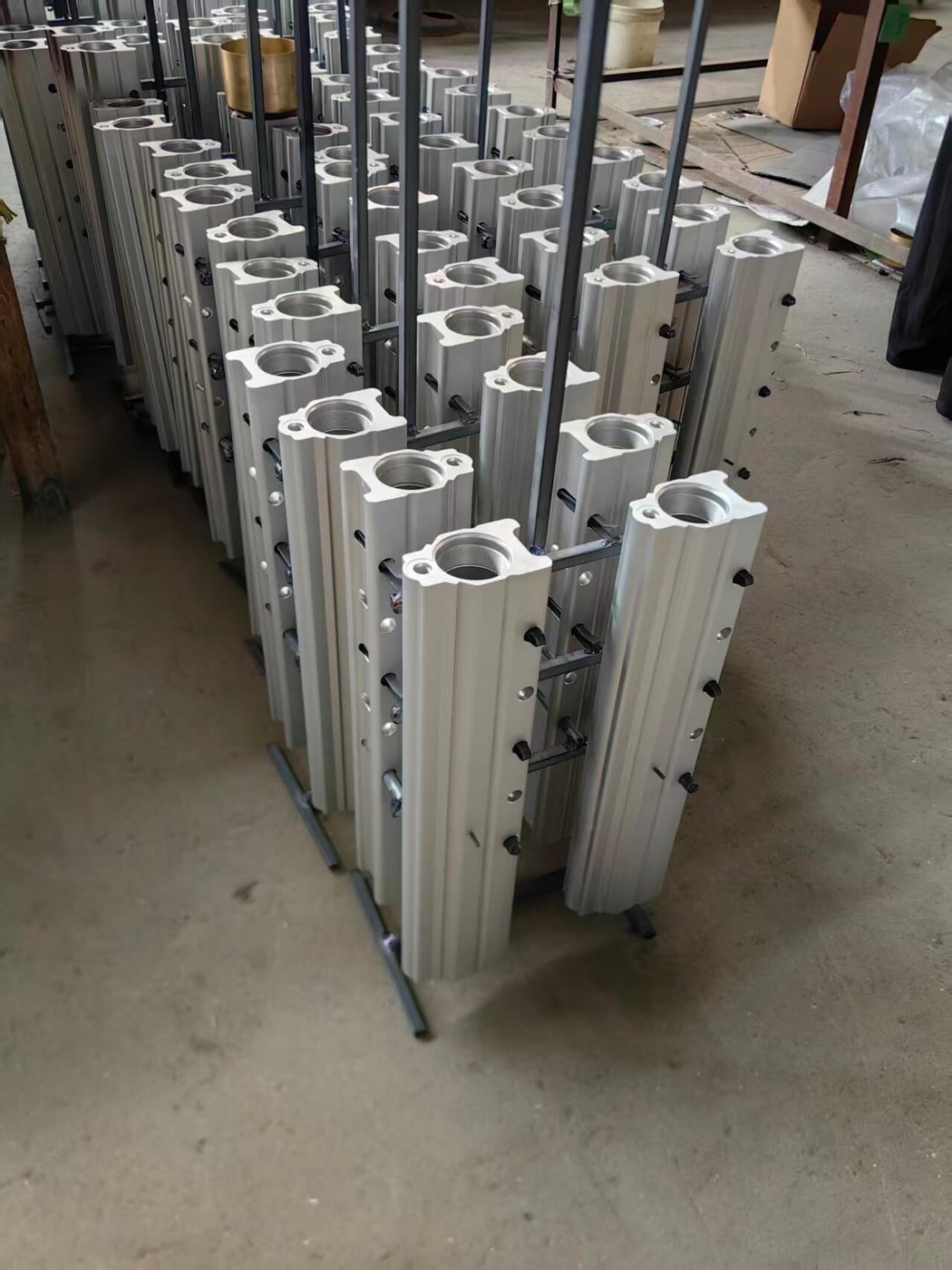
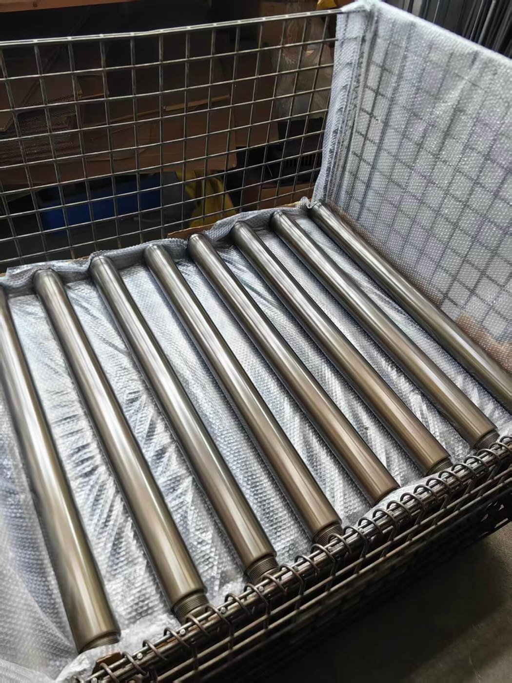
The long cylindrical parts make one point especially clear: the functional surface may extend far beyond an easily accessible measuring location. Define where the part works, where it will be measured and how it will be protected. For batches of small components, identification and handling deserve the same attention as the coating note.
Which parameters belong in the specification?
A good finish specification can be read by the machinist, the coating processor and the inspector without each person having to make a different assumption. These are useful starting fields for that shared definition.
| Parameter | How to state it | Why it matters |
|---|---|---|
| Substrate | Exact alloy, temper and material form | “Aluminum” alone does not define a consistent starting material. |
| Coating system | Applicable specification and revision, process type, approved treatment | Defines what is being supplied and prevents informal substitutions. |
| Oxide thickness | Target, tolerance and measurement locations in µm or inches | Connects the finish to the dimensional allowance and acceptance plan. |
| Surface texture | For example, Ra 0.8 µm on a marked face, only if the design requires it | State whether the requirement applies before or after the complete treatment. |
| Friction | Static or kinetic result, counterface, load, speed, environment and test method | A coefficient without test conditions is difficult to compare. |
| Wear and corrosion | Test method, specimen condition and pass/fail criteria | Separates measurable performance from general marketing language. |
| Masking and contact | Marked regions, boundary tolerance and permitted rack locations | Protects assembly features and makes witness marks intentional. |
Numerical examples in this article explain specification formats and dimensional calculations. They are not a universal process window or a guarantee of MileMetal coating capability.
Keep hardness units clear
HV and HRC refer to different hardness scales. A phrase such as “50–70 HV/HRC” does not define a usable requirement. If hardness is needed for acceptance, specify the method, load, specimen preparation and location. The Aluminum Anodizers Council also cautions that a hardness result cannot by itself prove wear resistance. AAC hardcoat application guideline.
For a sliding component, a well-chosen wear or friction test may answer a more useful question than a hardness comparison. Ask what the number will establish about the part before adding it to the drawing.
Plan for dimensional growth before cutting metal
Hard anodizing consumes some aluminum while building oxide above the original surface. A common planning approximation for Type III is that half of the total oxide thickness grows outward from each treated surface. An outside diameter therefore increases, while a coated bore becomes smaller. Chem Processing illustrates this relationship in its anodize buildup guide.
Outward growth per surface ≈ t ÷ 2 = 25 µm
| Feature | Before treatment | Approximate change | Illustrative result |
|---|---|---|---|
| Outside diameter, coated around its circumference | 20.000 mm | + 2 × 0.025 mm | 20.050 mm |
| Bore, both opposing walls coated | 20.000 mm | − 2 × 0.025 mm | 19.950 mm |
| Plate thickness, both faces coated | 10.000 mm | + 2 × 0.025 mm | 10.050 mm |
| Slot width, both internal walls coated | 8.000 mm | − 2 × 0.025 mm | 7.950 mm |
These calculations assume uniform oxide growth and exclude pretreatment removal, any additional polymer film and dimensional variation. Use them to understand direction and scale, then agree the actual allowance with the processor. For close fits, retain separate before-finish and after-finish requirements.
Do not infer the thickness deep inside a tube from a reading on its outside. NASA’s guidance highlights internal coverage and geometry as important limitations. A long working bore may need a specific process review and measurement plan. NASA PRC-5011, dimensional considerations.
Threads deserve their own instruction. Decide whether they are masked, treated to a defined allowance or handled through another agreed route. “All dimensions apply after finish” is helpful only if the manufacturing and finishing plans can actually deliver those dimensions.
Where the combination can be useful
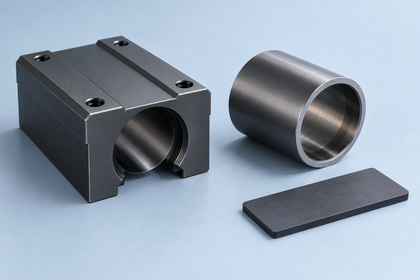
Guides and sliding mechanisms
Start with the contact pair and motion. State whether the concern is breakaway force, running friction or wear over repeated cycles. Include the actual mating material in evaluation.
Cylinder and valve-related components
Define the working bore, seal-contact area and finished clearance. Coating thickness on an accessible exterior face does not establish the condition of every internal feature.
Packaging and release surfaces
A lower-adhesion surface may help where process material sticks to a component. Test with the actual material, cleaning routine and operating temperature.
Automation wear parts
Guides, contact pads and replaceable inserts can be evaluated as a complete assembly. Track both component wear and any effect on the mating part.
Magnaplate’s Tufram product family is one commercial example of combining an aluminum oxide surface with proprietary polymers for friction and wear applications. Its published properties describe that supplier’s systems; they should not be transferred to an unspecified PTFE finish. Magnaplate Tufram overview.
Check the whole operating envelope
Record the load, speed, temperature, fluids, cleaning agents and expected duty cycle. A successful dry bench test may not represent an assembly exposed to abrasive contamination or a different counterface. Likewise, “self-lubricating” does not mean every mechanism can operate indefinitely without maintenance or without a lubricant required elsewhere in the design.
If the component has a food-contact, medical or other regulated role, include the required documentation for the specific coating and intended use in the enquiry. The presence of PTFE alone does not establish suitability for that application.
Inspect the finish against the job it needs to do
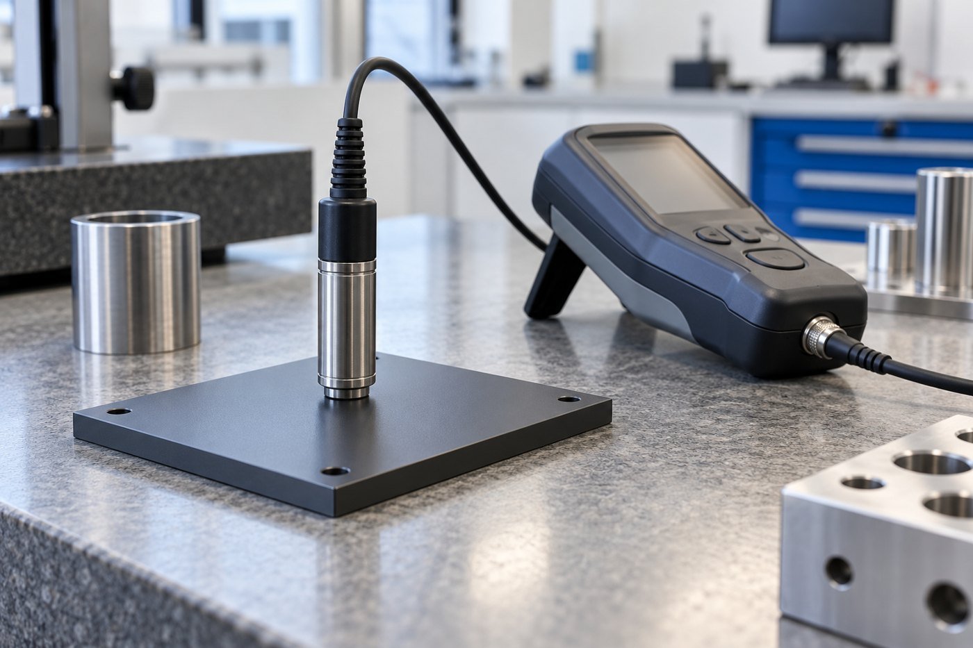
Start by agreeing which characteristics are checked on every production lot and which require a qualification exercise. Thickness, finished fit and friction are separate questions, so a single measurement should not be used as evidence for all three.
| Check | What it establishes | What to include in the record |
|---|---|---|
| Coating thickness | The coating at the measured location | Method, calibration, locations and individual readings |
| Finished dimensions | Conformance of bores, diameters and mating features | Drawing revision, acceptance limits and measured values |
| Surface condition | Texture, coverage, masking and permitted contact marks | Defined areas and agreed acceptance criteria |
| Friction and wear | Behavior under the specified test conditions | Counterface, load, speed, cycles, environment and results |
| Corrosion performance | Performance in the agreed exposure test | Test method, duration, specimen condition and failure criteria |
The AAC guideline identifies eddy-current measurement for anodic thickness and distinguishes application-specific tests. Place the measuring locations on the drawing where this helps avoid ambiguity. AAC inspection guidance.
For a new moving interface, use a representative first build to check assembly and operating behavior before committing to a larger quantity. Keep the accepted process and component revision linked together, so repeat orders reproduce the configuration that was evaluated.
Make the quotation request easy to act on
Send the component model and drawing with the alloy, temper, quantity and delivery needs. Mark the surfaces that move against another part, the surfaces that must be masked and the dimensions that are accepted after finishing. Add an assembly view if it explains the contact or access constraints.
- Approved hard anodic + PTFE process: [specification, revision, type and processor/process identifier].
- Total oxide thickness and tolerance: [value]; verify at [marked locations].
- PTFE treatment and any additional film allowance: [defined system].
- Final fits and surface requirements: [drawing features and limits].
- Masking and permitted rack contacts: [marked regions].
- Required inspection and performance evidence: [methods and acceptance criteria].
SAE AMS2482 addresses PTFE-impregnated or codeposited hard anodic coatings. If a standard is required, identify the applicable revision and process classification in the order rather than relying on a short finish name. SAE AMS2482 standard family.
For the underlying machining and hardcoat design discussion, see our Type III anodizing guide. Related applications include automation components and industrial equipment parts.
Frequently asked questions
Is hardcoat + PTFE the same as ordinary anodizing?
No. The request includes a hard anodic layer and a defined PTFE treatment. State both parts of the finish system, including the applicable specification and acceptance requirements.
Does PTFE always penetrate deeply throughout the oxide?
Do not assume that from the name. Ask the processor to identify its treatment and supporting technical data. Different commercial systems should not be treated as identical pore-filling processes.
Will PTFE eliminate the need for oil or grease?
That depends on the complete mechanism. Evaluate the intended contact pair, load, speed and environment, and retain any lubrication required by the equipment design.
Can I use a single coefficient of friction in the specification?
Include the test conditions with the value. Distinguish static from kinetic friction and define the counterface, load, speed and environment so the result can be interpreted.
How much does the finish change a bore?
With the illustrative 50% outward-growth assumption, a 50 µm oxide layer reduces a uniformly coated bore by about 50 µm on diameter. Actual allowances must account for the selected process, pretreatment and internal coverage.
Can a photograph confirm PTFE treatment?
No. Color and surface appearance do not establish coating chemistry or performance. Use the specified process documentation and inspection evidence.
What should I send MileMetal for a quotation?
Send the CAD model, dimensioned drawing, material and finish specification, quantity, critical fits, masking requirements and required records. Include the mating-part information if it explains the working surface.
Plan the machined part and the finish together
Share your aluminum component drawings with MileMetal. We can review the machining requirements and discuss the finishing scope, dimensional allowances and documentation needed for your enquiry.