
5 Electroplating Defects Analysis: Causes, Diagnosis and Prevention for Metal Parts
2026-09-15
Laser Welding vs MIG Welding: 6 Key Differences and How to Choose
2026-09-22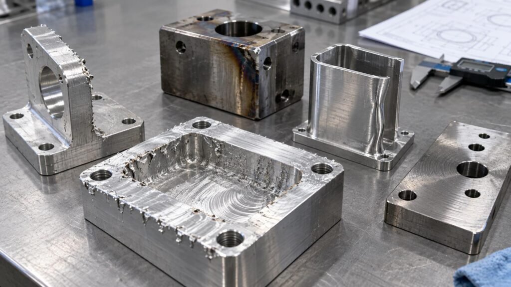
8 Major CNC Machining Defects Analysis: Causes, Solutions and Prevention
CNC machining defects are rarely random. Rough surfaces, burrs, dimensional drift, chatter, heat marks, warping, built-up edge and tool breakage usually point to a specific mix of cutting parameters, tooling, material behavior, fixturing and inspection control. This guide explains how to identify eight common CNC machining defects, why they happen and how to prevent repeat failures.
Why CNC Machining Defects Need Root Cause Analysis
A CNC part can look acceptable at first glance and still fail during assembly, coating, sealing or long-term use. A small burr can cut an O-ring. A slightly warped housing may leak after tightening. Chatter marks may reduce fatigue strength or create sealing problems. A hole that drifts by a few hundredths of a millimeter can stop a precision assembly from fitting.
The practical goal is not only to sort good parts from bad parts. The goal is to understand whether the defect came from design geometry, workholding, tool wear, speed and feed selection, coolant, chip evacuation, material stress, machine calibration or inspection setup. Once the source is known, the corrective action becomes much more direct.
8 Common CNC Machining Defects
The following eight categories combine the practical defect types highlighted by manufacturing guides from PremiumParts, 3ERP and RapidDirect, then reorganize them into a shop-floor diagnosis format for machined metal parts.
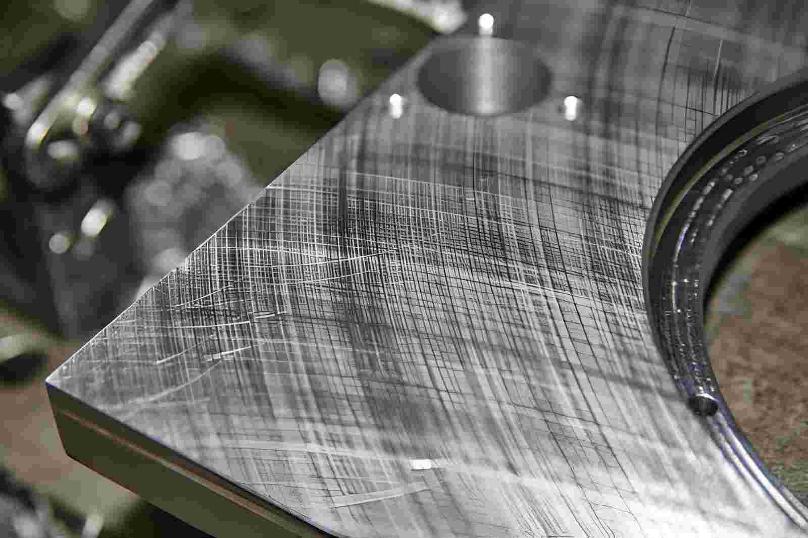
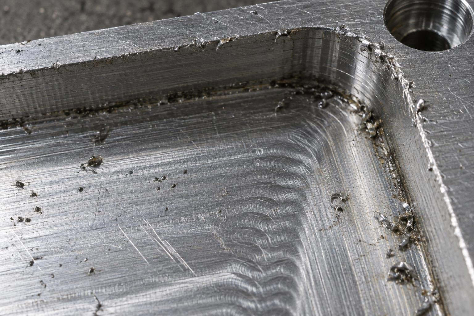
Rough texture, scratches, visible tool marks or inconsistent machining patterns.
Raised metal, feather edges or small chips left around pockets, holes and profiles.
Parts fall outside drawing tolerances for hole position, slot width, flatness or critical fits.
Regular wave patterns, ringing marks or uneven wall texture caused by unstable cutting.
Discoloration, work hardening, surface softening or heat-affected marks near cuts.
Thin walls, plates or housings move after roughing, finishing, unclamping or heat exposure.
Material welds to the cutting edge or loose chips scratch the machined surface.
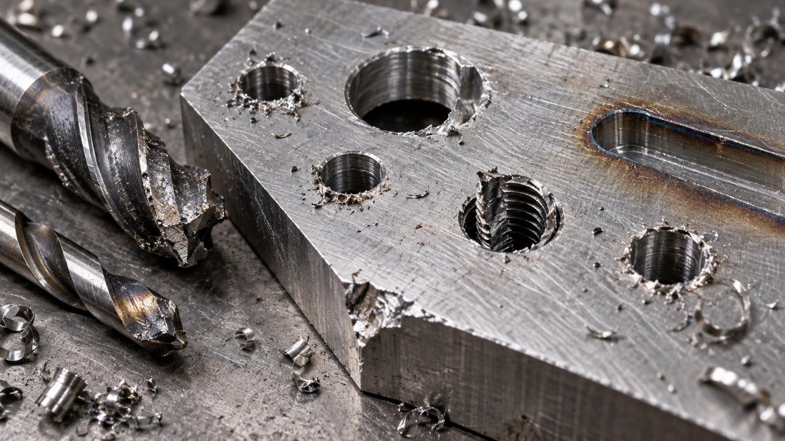
Broken drills, taps or end mills create oversize holes, torn threads or embedded fragments.
CNC Machining Defect Root Cause and Solution Matrix
Use this table as a practical troubleshooting starting point. The same symptom can have more than one cause, so the best diagnosis compares part location, tool number, setup, material batch and inspection history.
| Defect | Typical appearance | Likely causes | Corrective actions | Prevention focus |
|---|---|---|---|---|
| Poor surface finish | Rough texture, scratches, feed lines, uneven sheen or poor Ra value | Dull tool, wrong feed per tooth, excessive spindle speed, poor coolant, unstable tool path or chip recutting | Replace or sharpen tools, adjust speed/feed, improve coolant flow, use finish pass and confirm tool runout | Define required Ra, use proven finish parameters and inspect surface at first article |
| Burrs and sharp edges | Raised edges around holes, slots, pockets and profile exits | Ductile material, worn cutter, excessive feed, poor tool exit strategy, unsupported thin edges | Optimize tool geometry, add chamfer/deburr operation, reduce feed at exit, use climb milling where suitable | Add drawing edge-break requirements and standard deburring criteria |
| Dimensional inaccuracy | Out-of-tolerance holes, wrong pocket size, poor flatness or mismatched assembly fit | Machine calibration error, tool deflection, thermal expansion, fixture shift, incorrect datum setup or inspection error | Recalibrate machine, verify work offset, reduce tool overhang, add semi-finish pass, inspect with CMM or calibrated gauges | Control datum strategy, first-article inspection and in-process measurement frequency |
| Chatter and vibration marks | Regular waves, ringing patterns, inconsistent wall texture or noisy cutting | Low rigidity, excessive tool stick-out, weak clamping, thin-wall resonance, incorrect speed/feed combination | Shorten tool overhang, improve fixturing, change spindle speed, reduce radial engagement or use vibration-damping tools | Review setup rigidity and use stable machining strategies for deep pockets and thin walls |
| Burn marks and thermal damage | Blue, brown or dark discoloration; hardened surface; smeared or glazed metal | Excessive cutting heat, insufficient coolant, dull tool, too high speed, poor chip evacuation or material work hardening | Reduce cutting speed, increase coolant pressure, use coated sharp tools, improve chip evacuation and avoid rubbing cuts | Match coolant and tool coating to material, especially stainless steel, titanium and hardened alloys |
| Warping and distortion | Thin walls bend, plates bow, housings lift from inspection plate or flatness fails after unclamping | Residual stress release, uneven stock removal, aggressive roughing, weak support, heat buildup or poor clamping sequence | Stress-relieve material, rough both sides symmetrically, leave stock for finish pass, support thin walls and control heat | Plan machining sequence around stress balance, not only cycle time |
| Built-up edge and chip recutting | Torn surface, random scratches, poor finish, material stuck to tool edge or chip dents | Material welding to tool, inadequate lubrication, low cutting speed for ductile alloys, poor chip evacuation in deep pockets | Use suitable coating, increase cutting speed where appropriate, apply high-pressure coolant or air blast and clear chips | Choose material-specific tooling and chip evacuation strategy before production |
| Tool breakage and hole defects | Broken tap, oversized or off-center hole, torn thread, chipped edge, embedded tool fragment or incomplete feature | Excessive load, wrong peck cycle, poor chip removal, tool wear, insufficient tool strength or incorrect pilot hole | Review tool life, reduce depth of cut, use correct drill/tap cycle, confirm pilot size and stop production after abnormal load | Use tool life monitoring, spindle load alarms and first-piece hole/thread inspection |
Main Root Cause Groups Behind CNC Defects
1. Cutting parameter mismatch
Speed, feed, depth of cut and step-over must match the material, tool diameter, flute count, coating and machine rigidity. Too aggressive a setup can cause chatter, tool deflection, overheating and tool breakage. Too conservative a setup can cause rubbing, built-up edge and poor surface finish.
2. Tool condition and tool selection
A sharp tool can still be the wrong tool. Flute geometry, coating, helix angle, corner radius and tool length all change cutting stability. Tool wear should be tracked by material and operation, not only by total machining time.
3. Workholding and datum control
Many dimensional defects come from the setup instead of the program. Weak clamping, inconsistent locating surfaces, part movement, long unsupported features and poor datum selection can all create repeatable but hidden errors.
4. Material stress and machinability
Rolled plate, cast blanks, heat-treated alloys and thin-wall parts can move after material is removed. Aluminum may burr or smear, stainless steel may work harden, titanium may generate heat, and brass may machine cleanly but still requires sharp tools for precision holes.
5. Chip evacuation and coolant control
Deep pockets, blind holes and narrow slots can trap chips. If chips are recut, they scratch the surface and increase tool wear. If heat is not removed, the workpiece and tool can expand, burn, harden or lose dimensional stability.
High-pressure coolant, air blast, optimized peck cycles and tool paths that allow chips to escape are often more effective than simply slowing the program.
Material-Specific CNC Defect Diagnosis
The same machining defect can have different root causes depending on the material. A burr on soft aluminum, a burn mark on stainless steel and a distorted thin titanium bracket should not be corrected with the same parameter change. Material behavior must be part of the defect review.
| Material | Common defect tendency | Why it happens | Practical control method |
|---|---|---|---|
| Aluminum alloys | Burrs, built-up edge, smeared surface, scratches from chips | Aluminum is ductile and can weld to the cutting edge when lubrication, tool coating or chip evacuation is poor. | Use sharp polished tools, suitable coatings, high chip clearance, stable coolant or air blast and defined deburring rules. |
| Stainless steel | Work hardening, burn marks, rapid tool wear, poor finish | Stainless steel retains heat and becomes harder when the tool rubs instead of cutting cleanly. | Use rigid setup, sharp coated tools, positive cutting action, controlled speed, sufficient coolant and avoid dwelling. |
| Carbon steel and alloy steel | Tool wear, dimensional drift, heat tint, hard spots after heat treatment | Hardness variation and abrasive carbides increase cutting load and tool wear, especially in interrupted cuts. | Confirm hardness before machining, select carbide grade carefully, monitor tool life and separate roughing from finishing. |
| Brass and copper | Fine burrs, tearing, poor chip control, surface dents | Soft non-ferrous metals may grab tools or deform locally if tool geometry is not matched to the alloy. | Use material-specific rake geometry, sharp drills and taps, controlled feed and careful handling after machining. |
| Titanium alloys | Heat damage, tool chipping, built-up edge, poor dimensional stability | Titanium has low thermal conductivity, so heat stays near the cutting edge and accelerates tool failure. | Use conservative engagement, high-pressure coolant, rigid tooling, short tool overhang and frequent tool inspection. |
| Engineering plastics | Melting, fuzzing, warping, poor hole quality | Plastics soften with heat and can move under clamping pressure or absorb moisture before machining. | Use sharp tools, lower heat input, proper support, stress-relief where needed and avoid over-clamping thin sections. |
Corrective Action Workflow: From First Defect to Stable Production
When a CNC defect is found, the response should be systematic. Reworking the part or slowing the machine may solve one batch, but stable production requires a closed-loop process that links defect evidence to machining parameters, tooling, fixturing and inspection data.
Stop mixing suspect parts with accepted parts. Separate by machine, setup, shift, material batch and inspection result.
Mark the exact feature, surface, tool path, direction of marks and whether the defect repeats at the same location.
Review tool number, tool life, offset changes, spindle load, coolant condition, fixture position and operator notes.
Run a controlled sample, inspect critical features and keep the corrected parameters in the job record.
What to include in a CNC defect report
A useful defect report should include more than photos. Add drawing revision, material lot, machine number, fixture number, tool number, operation number, inspection equipment, actual measurement data and the number of affected parts. For surface defects, include lighting angle and magnification level. For dimensional defects, include datum setup and measurement method.
When to update the drawing or process plan
If the same type of defect appears repeatedly, the issue may not be only production control. The drawing may need clearer edge-break notes, more realistic surface finish requirements, larger internal corner radii, added datum clarification, wider non-critical tolerances or a different finish sequence. For repeat OEM parts, these updates reduce cost and improve consistency across future orders.
How to Prevent CNC Machining Defects Before Production
Defect prevention starts before the machine cycle begins. The most effective suppliers review drawings, material condition, tolerance stack-up, fixture access, tool paths, finishing requirements and inspection methods together.
Check deep pockets, sharp internal corners, thin walls, small holes, difficult datum schemes and tight tolerance stacks.
Choose suitable tools, reduce overhang, support the part and balance stock removal to control stress.
Inspect dimensions, threads, burrs, surface finish, flatness and critical fit points before running the batch.
Record tool life, machine, fixture, coolant, inspection result and any defect location for repeat jobs.
- Add realistic edge-break and deburring notes to the drawing instead of relying on vague appearance expectations.
- Use larger internal corner radii where possible to reduce tool deflection and avoid excessive deep-pocket loading.
- For thin-wall parts, allow roughing, stress relief or staged finishing when flatness and wall accuracy are important.
- Define surface roughness, visual limits and post-processing expectations before production.
- Use CMM, calibrated gauges or functional fixtures for critical features instead of relying only on manual checks.
- Stop and investigate when defects cluster by one tool, one fixture position, one material batch or one machine shift.
Inspection Methods for CNC Machining Defects
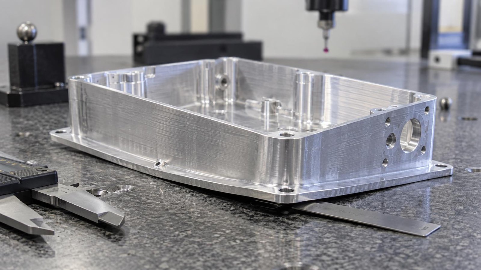
Inspection should match the defect risk. A cosmetic bracket may need visual and burr checks; a sealing housing may need flatness, surface roughness and leak-related dimensions; a shaft or bushing may need roundness, diameter, concentricity and finish checks.
| Inspection method | What it checks | Best use case |
|---|---|---|
| Visual inspection and limit samples | Burrs, scratches, chatter, burn marks, dents and handling damage | Customer-facing parts, anodized parts and parts with appearance requirements |
| CMM inspection | Hole position, profile, flatness, perpendicularity, true position and complex datum relationships | Precision machined housings, brackets, fixtures and aerospace-style tolerance schemes |
| Go/no-go gauges and thread gauges | Functional fit, hole size, threads and assembly-critical features | Production batches where fast repeat checks are needed |
| Surface roughness tester | Ra or other roughness values on sealing, sliding or cosmetic surfaces | Parts with sealing faces, bearing contact, medical, optical or finishing requirements |
| Flatness and runout checks | Warping, bowing, concentricity, shaft runout and assembly alignment | Thin plates, housings, shafts, rotating parts and precision mating surfaces |
FAQ About CNC Machining Defects
What is the most common CNC machining defect?
Surface finish problems and burrs are among the most common because they can appear across many materials and operations. However, the most costly defects are often dimensional errors, warping, tool breakage and hidden hole or thread problems.
Can surface finishing hide CNC machining defects?
Processes such as bead blasting, anodizing or powder coating can reduce the visual impact of minor tool marks, but they should not be used to hide functional defects. Burrs, poor flatness, oversize holes, cracks and severe chatter should be corrected before finishing.
Why do thin CNC machined parts warp?
Thin parts warp when residual stress is released, when stock is removed unevenly, when clamping force bends the part or when heat builds up during machining. Balanced roughing, stress relief, good support and staged finishing help reduce distortion.
How can buyers reduce CNC machining defects?
Share complete drawings, material requirements, tolerance priorities, cosmetic limits, surface finish needs and end-use conditions. Ask the supplier to review manufacturability, inspection method and critical features before production starts.
Need CNC Machined Parts With Better Defect Control?
Milemetal supports CNC machining, CNC milling, CNC turning, surface finishing and inspection planning for custom metal parts. Send your drawing, material and application requirements for engineering review.
References: This article was written as an original Milemetal guide after reviewing CNC machining defect discussions from PremiumParts, 3ERP and RapidDirect. The structure, examples and recommendations have been rewritten for OEM CNC machined metal parts.