
CUSTOM PARTS FOR MOTION & AUTOMATION
CNC Machining for Robotics & Automation
Build your next robotic assembly around clearly defined mechanical interfaces. MileMetal supplies custom machined components from your drawings, including structural parts, mounting brackets, shafts and housings for robotics projects.
Send your CAD files and critical requirements for a review of materials, machining, finishing and inspection—from evaluation parts to repeat production.

FROM A COMPONENT TO A WORKING ASSEMBLY
Machining decisions that support your robot design
A robot combines many mechanical interfaces: motor registers, bearing seats, locating pins, structural joints and tool attachments. Each part needs to work with its neighbors. A useful manufacturing review starts with those relationships, then defines the features that need close control.
For engineering teams
Identify how the part locates, transfers load and interfaces with purchased hardware. Share the relevant assembly envelope so tool access, cable routes, fastener clearance and finish allowances can be considered together.
A precise component drawing helps translate design intent into a practical machining and inspection plan.
For sourcing teams
Provide the released model, drawing revision, order quantities and delivery needs as one package. Separate required inspection documents from optional checks, and identify any approved material or finish alternatives.
This gives the quotation a defined scope and makes repeat orders easier to compare.
COMPONENT GALLERY
Custom machined parts for robotic mechanisms
The photographs below come from MileMetal’s existing product library. They illustrate part forms and machining features; the material, tolerances and application of your order are established by its approved drawing.

Structural links & joint supports
Pocketed aluminum structures, joint frames and mounting interfaces combine load paths with weight reduction. Review local wall thickness, access to internal corners and the location of critical assembly faces.
Identify functional datums before adding cosmetic requirements or removing additional material.

Motor brackets & equipment mounts
Brackets and plates locate motors, sensors and auxiliary equipment. Mounting hole patterns, registers, seating faces and access for installation should be defined in relation to the mating component.
Include the purchased motor or sensor interface drawing when it controls the fit.

Shafts, pins & turned interfaces
Stepped shafts, spacers, sleeves and locating pins provide rotational or positioning interfaces. Diameters, shoulders, thread details and runout requirements need a coordinated definition.
Specify any heat treatment or grinding requirement together with the final acceptance condition.
Drive and sensor enclosures
Pockets, bearing interfaces, cable exits and cover patterns can share a compact part. Distinguish sealing or alignment surfaces from appearance-only surfaces, and include space for connectors and tools.
Gripper fingers & tool adapters
Custom jaws, adapter plates and fixture elements connect the robot to its task. Describe workpiece contact areas, mounting geometry and replacement requirements. The application designer defines gripping force and operating loads.
Guide plates & fixture bases
Rail seats, dowel holes and reference edges support positioning assemblies. Define how the plate is mounted and inspected; a free plate and a bolted-down plate may require different acceptance conditions.
ROBOTICS APPLICATIONS
Support for different motion architectures
Industrial robot assemblies
Joint supports, mounting interfaces and peripheral tooling connect the robot to the production cell. Review stiffness requirements, service access and the surfaces used to establish alignment.
Collaborative robot tooling
Tool adapters and compact end effectors must fit within the permitted envelope and mass budget. Specify edge conditions and accessible surfaces. Component machining does not replace the completed system’s safety assessment.
Humanoid and articulated mechanisms
Lightweight links, joint frames and compact mounting parts often combine several interfaces in limited space. Share assembly CAD to identify inaccessible fasteners, thin sections and conflicting datum choices early.
Mobile robots and automation modules
Sensor mounts, drive supports, fixture plates and equipment brackets require defined interfaces for installation and maintenance. Include environmental conditions when they influence material, coating or sealing choices.
DESIGN FOR MANUFACTURING
Review the details that can disrupt assembly
Start with the locating scheme
Identify which face, bore or pin establishes the part’s position. Bolt holes that provide clearance do not necessarily locate an assembly. A clear datum system allows machining and inspection to reference the same functional features.
Balance weight with manufacturability
Deep pockets, long thin walls and unsupported ribs can make machining and measurement more sensitive to deflection. Keep the intended stiffness and mass limits in the design brief so any proposed geometry change can be assessed by the responsible engineer.
Allow for the finished condition
Anodizing, plating and heat treatment can affect dimensions or surface condition. Identify masked areas and define the features that must be accepted after finishing, especially bearing fits, threaded interfaces and locating diameters.

| Functional feature | What the drawing should define | Why it matters |
|---|---|---|
| Motor or bearing register | Size, fit, datum relationship and finished condition | Controls mating engagement and alignment |
| Locating-hole pattern | Hole sizes, positional requirement, datum references and pattern definition | Separates positioning features from clearance fasteners |
| Mounting or rail seat | Flatness, surface texture and inspection restraint condition | Provides a defined basis for seating and alignment checks |
| Rotating shaft | Bearing-seat dimensions, shoulder geometry and specified runout | Relates the rotating interfaces to the selected datum axis |
| Thin-wall frame | Minimum wall, local radii, edge requirements and permitted deviations | Guides workholding, cutter access and handling |
| Threaded feature | Thread designation, class where applicable, usable depth and entry detail | Avoids confusion between drill depth and functional engagement |
MATERIAL & FINISH SELECTION
Match the material to the job each part performs
Choose a grade and condition based on the design’s loads, mass, environment and assembly requirements. The options below are discussion points for an RFQ; availability and suitability are confirmed for each project.
| Material option | Potential use | Key review points |
|---|---|---|
| Aluminum 6061-T6 | Brackets, frames, mounting plates and housings | Wall stability, surface finish, cosmetic expectations and coating allowances |
| Aluminum 7075-T6 | Specified structural parts where the design calls for this alloy | Required strength condition, environment, stock form and finishing compatibility |
| Stainless steel 304 / 316 | Specified hardware, supports and interfaces exposed to demanding environments | Exact grade, corrosion conditions, surface treatment and mass |
| Alloy or carbon steel | Shafts, pins and wear-related components | Grade, hardness, heat-treatment sequence and any final grinding requirement |
| POM / acetal | Guides, bushings, spacers and selected nonmetallic parts | Load, creep, temperature and dimensional stability |
| PEEK or other specified polymer | Specialized insulating or environmental interfaces | Exact grade, reinforcement, operating conditions and machining tolerances |
Anodized aluminum
Specify finish type, color, coating thickness requirements and masked features. Appearance acceptance should account for the alloy and process. Keep critical fits separate from general cosmetic surfaces.
Stainless surface treatment
Define any passivation or other treatment by the required specification. Surface cleaning, visible appearance and corrosion-related requirements are different acceptance questions.
Controlled edges & surfaces
Replace a vague “remove all sharp edges” note with appropriate limits where edges perform a function. Identify contact surfaces, thread entries and cable-adjacent edges that need particular attention.
SPECIFICATION EXAMPLES
Turn “high precision” into measurable requirements
The numbers below illustrate how a requirement can be written. They are not universal design recommendations or a statement of guaranteed machining capability. Final feasibility, methods and acceptance values are agreed from the complete drawing.
| Drawing item | Illustrative entry | Additional definition needed |
|---|---|---|
| Critical linear dimension | 40.00 ±0.05 mm | Feature location, functional purpose and measurement condition |
| Mounting-face flatness | 0.05 mm across the marked face | Face boundary, free or restrained condition and final process stage |
| Surface texture | Ra 1.6 μm on a designated seat | Measurement direction, area and any additional texture criteria |
| Thread | M6 × 1, with specified class and usable depth | Blind-hole clearance, entry chamfer and gauge requirement |
| Order planning | Prototype quantity plus expected repeat quantity | Released revision, requested delivery and inspection documentation |
Do not assign the same tight tolerance to every feature. Focus close control on the interfaces that affect fit and function. For a bearing seat or locating pin, define the fit using the mating-component requirements instead of selecting an arbitrary tolerance.
FROM CAD TO DELIVERED PARTS
A manufacturing route built around the released drawing
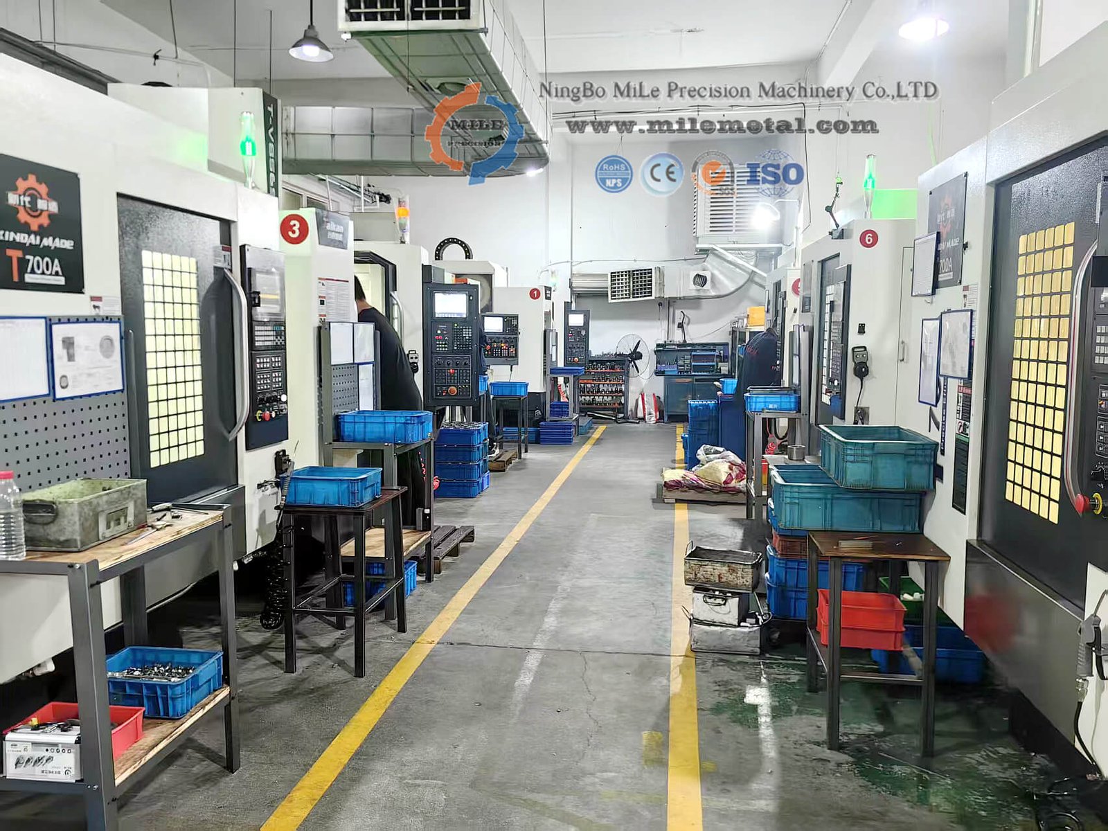
Milling suits pockets, faces and hole patterns; turning suits cylindrical interfaces and shoulders. Some parts combine both. Setup planning should preserve the relationships between functional surfaces, while accounting for access, material removal and the finishing sequence.
Share the prototype objective and expected follow-on demand. An evaluation part may prioritize a design question, while a repeat order needs a stable revision, inspection plan and packaging definition.
Define the order
Submit models, controlled drawings, quantity, material and finish requirements. Identify critical features and mating interfaces.
Review & agree
Resolve drawing questions and confirm manufacturing scope, inspection records, pricing and schedule.
Machine & finish
Produce to the released requirements with the agreed process sequence and checks on designated features.
Inspect & pack
Complete the specified verification and protect finished surfaces, threads and slender features for delivery.
VERIFICATION AT THE RIGHT STAGE
Define inspection around assembly-critical features
Agree on the measurement method and report scope before production. Different characteristics need different evidence: a thread gauge does not verify a hole’s location, and a dimensional report does not prove the completed robot’s motion accuracy.
- Material and revision: specify the required material documents and identify the drawing used for the order.
- Geometric relationships: define datums, locating dimensions and any CMM reporting requirements.
- Fits and threads: identify gauge requirements and whether checks follow finishing.
- Surface condition: specify texture, coating, edge treatment and cosmetic acceptance where relevant.
- Shipment condition: agree on part identification, separation and protection.

Machine-level positioning accuracy, payload, fatigue life and system safety depend on the complete design and operating conditions. Validate the assembled mechanism against its own requirements; component inspection provides one part of that evidence.
PROTOTYPE TO REPEAT PRODUCTION
Use the first build to close the right questions
Before approving a repeat order
Record the outcome of fit checks, assembly access and finish evaluation. If a mounting hole moves or a spacer changes, release the revised files together rather than combining an old model with a new drawing.
List the characteristics that must be rechecked after each design change. Preserve the approved material and finishing requirements unless a substitution has been reviewed.
Before comparing quotations
Confirm that each quote covers the same grade, revision, finish and inspection scope. A low unit price may exclude documentation, secondary operations or packaging that your assembly needs.
Separate essential requirements from preferences, and include likely reorder quantities so the supplier can evaluate the production approach.
START YOUR ROBOTICS PROJECT
Send the component files. Define the next build.
Share the parts you need, the interfaces that matter and the delivery target. MileMetal can review your machining requirements and prepare a quotation around the agreed scope.
PROJECT QUESTIONS
Robotics CNC machining FAQs
Which robotics parts can I submit for a quotation?
Send drawings for brackets, structural components, mounting plates, housings, shafts, spacers, fixture elements and similar mechanical parts. The review establishes feasibility and the required manufacturing route for the actual geometry.
Can I start with a prototype quantity?
Include the quantity needed for the first build and the anticipated repeat-order demand. Pricing and scheduling depend on the part, stock, setup, finishing and inspection requirements. The quotation will confirm the available scope.
Do you need assembly drawings?
A component drawing may be enough for a simple part, but assembly context helps when adjacent parts control access, alignment or fits. Supply mating dimensions and the relevant envelope rather than relying on a photograph to define a precision interface.
Can the parts be anodized?
Include the required anodizing specification, appearance expectations and any masking notes in the RFQ. Critical dimensions should state whether they apply before or after treatment. Finishing scope is confirmed in the quotation.
How should bearing fits and locating holes be specified?
Use the mating-component requirements and the design’s locating scheme. State the size, fit or tolerance, geometric relationships and finished condition. A generic tolerance on the entire part does not adequately define every functional interface.
Are inspection reports included?
Request the report format, characteristics, sampling and material documentation you need before ordering. The agreed scope determines the supplied records. Additional system-level testing requires its own procedure and responsibility.
Are the gallery images a single customer case study?
No. They are existing MileMetal product and facility photographs selected to explain relevant component types and processes. This page presents robotics machining services rather than a claim about a specific customer’s project results.
What should I provide for a repeat order?
Confirm the part number, released model and drawing revision, material, finish, quantity and delivery requirement. Include any approved changes from the previous build and the inspection documentation needed with the shipment.
Ready to review your robot component drawings?
Bring the functional requirements into the quotation from the beginning.