
Metal Stamping Services for Custom Sheet Metal Parts
Milemetal provides custom metal stamping services for brackets, clips, shields, covers, terminals, washers, springs, mounting plates and precision sheet metal components. We support prototype validation, tooling review, progressive die stamping, blanking, piercing, bending, forming, embossing, drawing, tapping, hardware insertion and secondary finishing.
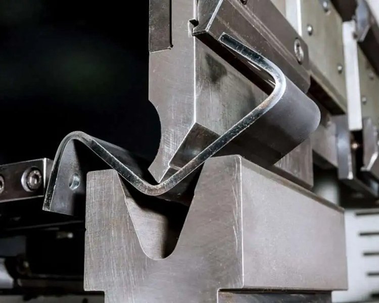
Custom Metal Stamping Capabilities
Metal stamping uses a press and die tooling to cut and form sheet metal into repeatable parts. It is well suited for components that need consistent geometry, low unit cost at volume and features such as holes, slots, tabs, bends, embosses, ribs, offsets, shallow drawn forms and integrated mounting details.
Compared with laser cutting and press brake bending, stamping requires more upfront tooling planning but can reduce unit cost dramatically once production volume increases. For new designs, Milemetal can help review whether a part should start with laser-cut prototypes, soft tooling, compound dies or progressive die stamping.
Flat profiles, holes, slots, tabs, washers, contacts, shields and precision cut features.
Flanges, clips, brackets, offsets, lances, ribs, tabs and spring-style features.
High-repeatability production where multiple cutting and forming stations run in sequence.
Shallow cups, shells, covers and formed metal shapes when material flow is controlled.
Raised logos, stiffening ribs, countersinks, dimples, locating features and local thickness control.
Deburring, tapping, spot welding, PEM hardware, plating, powder coating and final inspection.
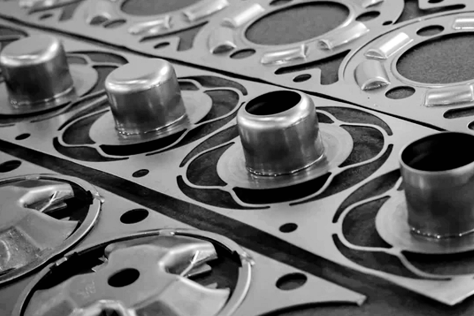
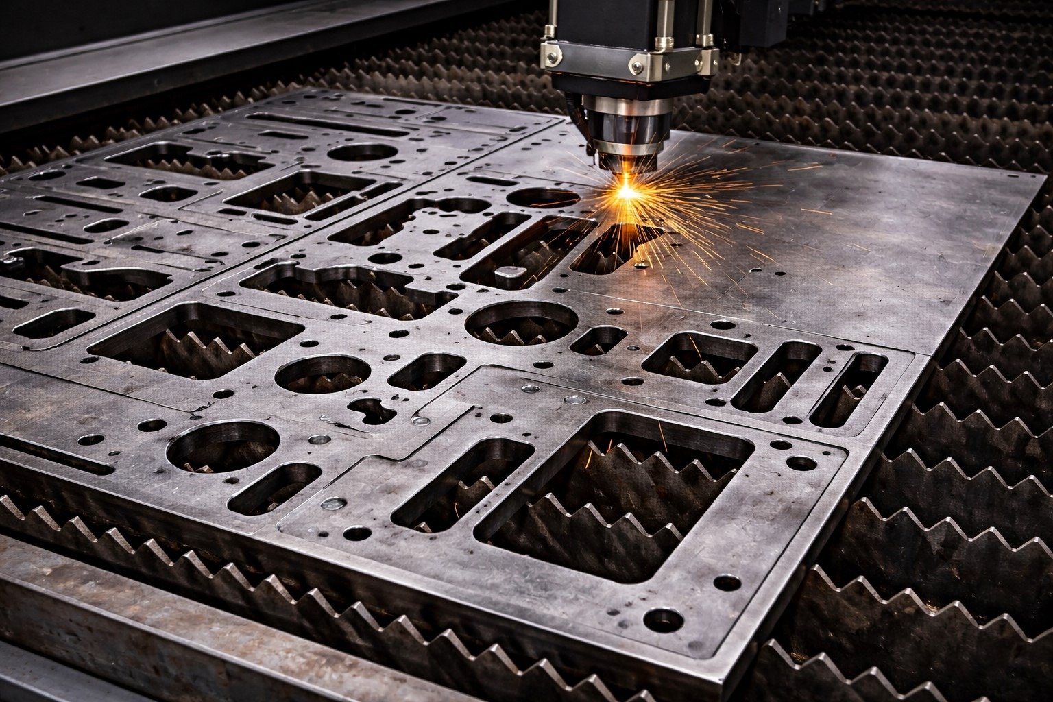
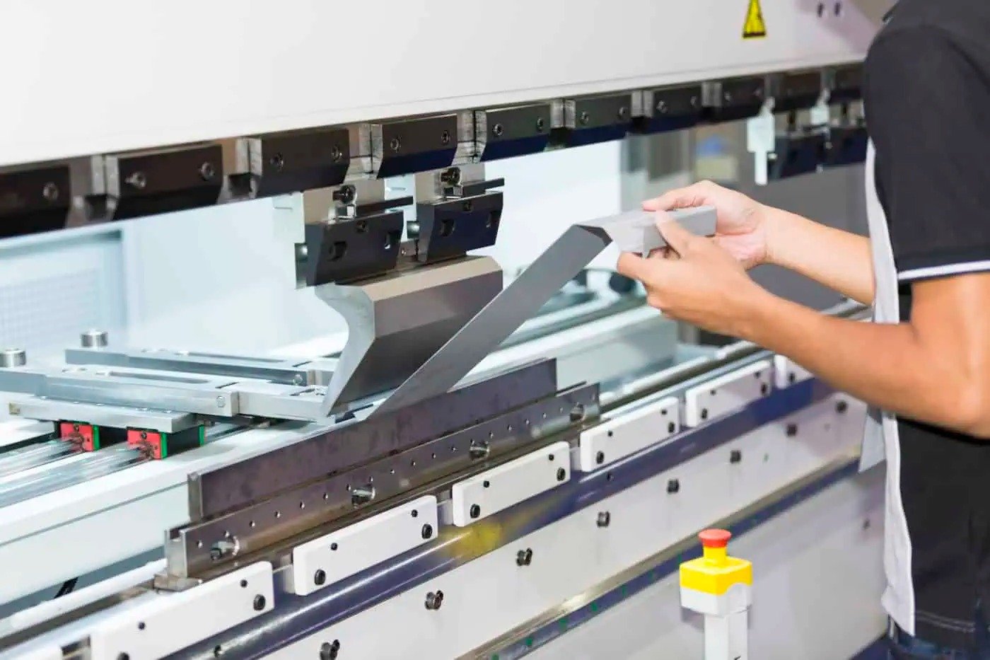


Stamped Metal Parts Gallery
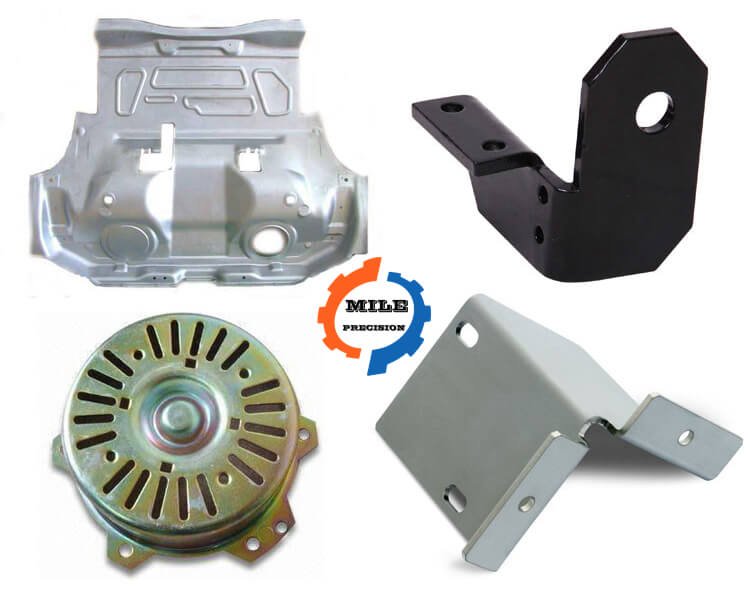
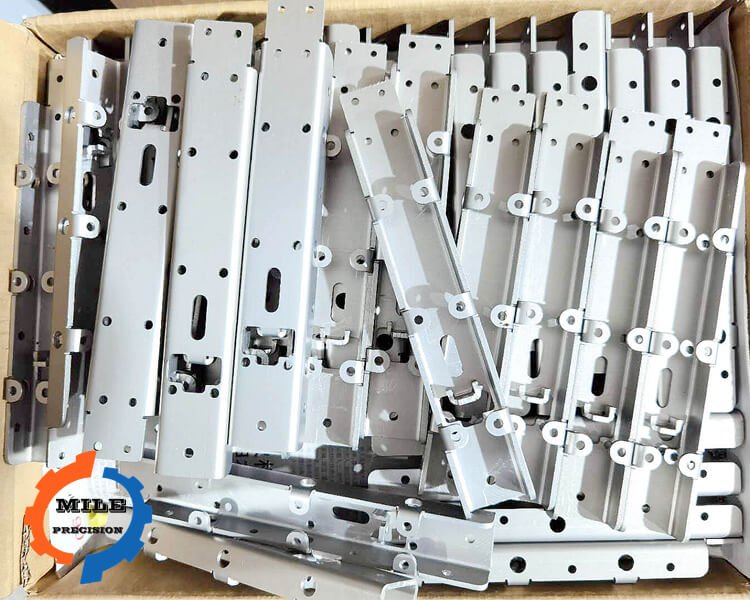
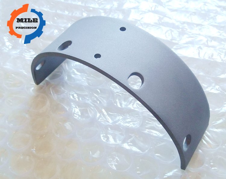
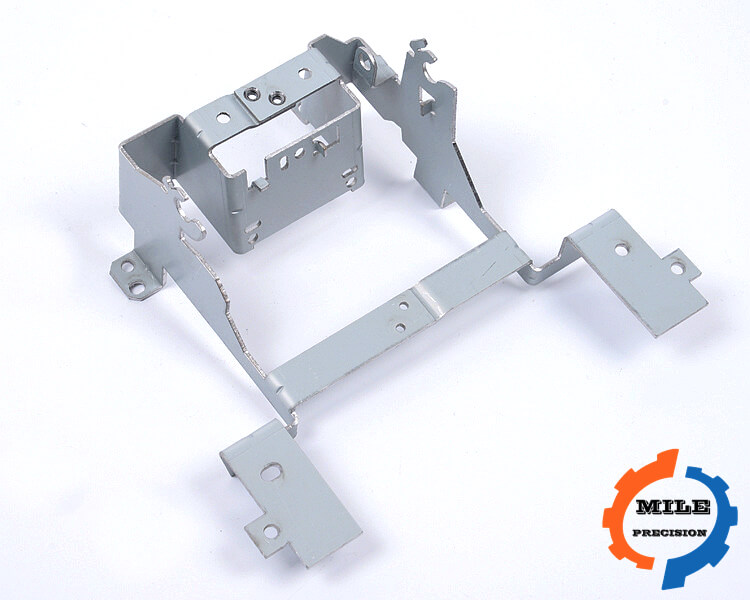
The product gallery below shows typical stamped and sheet metal part forms, including flat blanks, formed brackets, shields, covers, plated steel parts, aluminum panels and conductive copper or brass components. Similar geometries may be produced by stamping, laser-cut prototyping, press brake forming or secondary CNC operations depending on quantity and tolerance.




Metal Stamping Process Flow
DFM review
Confirm material, thickness, part geometry, tolerance, burr direction, finish and expected annual volume.
Tooling plan
Select prototype route, simple die, compound die, forming die or progressive die based on volume and features.
Stamping run
Blank, pierce, bend, form, coin, emboss, draw or cut off the part using press and die tooling.
Finish and QC
Deburr, clean, plate, coat, insert hardware, inspect dimensions and package parts for shipment.
Metal Stamping Process Comparison
Stamping can be simple or highly automated. The right method depends on geometry, volume, material thickness, dimensional tolerance, tooling budget and how many features must be formed in one production sequence.
| Stamping process | What it does | Best for | Typical volume fit | Design notes |
|---|---|---|---|---|
| Blanking | Cuts the outside profile from sheet or strip | Washers, plates, brackets, shields and flat blanks | Low to high depending on tooling | Edge quality, burr direction and die clearance should be defined. |
| Piercing / punching | Creates holes, slots, louvers and internal cutouts | Mounting holes, ventilation, tabs and terminals | Medium to high | Minimum hole size and hole-to-edge spacing depend on thickness and material. |
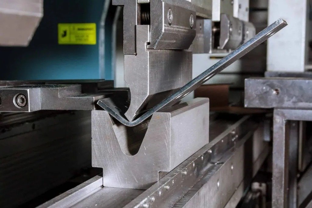
| Bending / forming | Creates flanges, offsets, clips, tabs and channels | Brackets, clips, spring contacts and mounting parts | Prototype to high volume | Springback, bend radius and grain direction affect accuracy. |
| Progressive die stamping | Moves strip through multiple stations in one die set | High-volume parts with repeated cut and form features | High | Higher tool cost, low unit cost, stable repeatability after tool validation. |
| Compound die stamping | Performs multiple cutting actions in one press stroke | Flat precision parts with accurate relationship between features | Medium to high | Useful when concentricity or hole-to-profile accuracy is important. |
| Deep drawing | Forms sheet into cup, shell or shallow drawn geometry | Covers, caps, cans, housings and formed shells | Medium to high | Draw ratio, material ductility, lubrication and corner radius are critical. |
| Coining / embossing | Compresses or raises local geometry | Logos, stiffening ribs, countersinks, dimples and contact areas | Medium to high | Requires higher local force and careful tool wear control. |
When to Choose Stamping Instead of Laser Cutting and Bending
Once the design is stable, stamping can reduce unit cost and cycle time for repeated production runs.
Tabs, lances, embosses, ribs, offsets and formed clips can be produced directly in the die.
For early designs, laser cutting and press brake bending can validate geometry before investing in hard tooling.
Progressive dies combine cutting, forming and cutoff operations for high-volume production.
Tapping, welding, PEM hardware, plating and deburring can complete stamped parts after the press operation.
Stainless, carbon steel, aluminum, brass, copper and spring materials are common stamped part materials.
Metal Stamping Design Parameters
The values below are practical starting points for design review. Final limits depend on material grade, temper, thickness, press capacity, die clearance, bend tooling, part geometry and inspection requirement.
| Parameter | Typical guideline | Why it matters | Risk if ignored |
|---|---|---|---|
| Material thickness | Approx. 0.2-6.0 mm for many precision stamped sheet parts | Controls press tonnage, die clearance, stiffness and feature limits | Cracking, poor flatness, high tool wear or excessive cost. |
| Inside bend radius | Often 1T or larger for early review; tighter bends need material confirmation | Prevents cracking and supports repeatable bend angles | Cracks on outside bend, springback or inconsistent forming. |
| Minimum hole diameter | Usually at least 1T for many punched holes; smaller holes need review | Protects punch strength and reduces breakage | Punch breakage, burrs, distorted holes or high tool maintenance. |
| Hole-to-edge distance | At least 1.5T to 2T when possible | Prevents edge distortion and weak sections | Tearing, bulging, poor edge quality or part deformation. |
| Hole-to-bend distance | At least 2.5T + bend radius when possible | Reduces distortion during forming | Elongated holes, assembly mismatch and rework. |
| Burr direction | Define functional side, cosmetic side and deburring requirement | Important for assembly, sealing, electrical contact and handling | Sharp edges, interference, poor contact or safety issues. |
| Grain direction | Review for bends, springs and highly formed areas | Material can crack more easily when bent across unfavorable direction | Cracking, inconsistent spring behavior and early fatigue. |
| Tooling allowance | Plan pilot holes, carrier strip, scrap bridges and forming clearance | Progressive dies need strip layout and stable material feed | Unstable feeding, poor repeatability or avoidable scrap. |
Metal Stamping Material Options
| Material | Advantages | Stamping behavior | Common finishes | Typical stamped parts |
|---|---|---|---|---|
| Low carbon steel | Cost-effective, strong, easy to form and weld | Excellent for general stamping | Zinc plating, nickel plating, powder coating, painting | Brackets, plates, clips, covers and hardware |
| Stainless steel 301 / 304 / 316 | Corrosion resistance and good appearance | Higher springback and tool wear than mild steel | Passivation, polishing, brushing, electropolishing | Spring clips, shields, food equipment parts and covers |
| Aluminum 5052 / 3003 / 6061 | Lightweight and corrosion resistant | Good formability for 5052 and 3003; 6061 needs bend review | Anodizing, powder coating, brushing, painting | Lightweight brackets, covers, panels and enclosures |
| Brass | Good conductivity, corrosion resistance and decorative appearance | Good for contacts, terminals and formed hardware | Nickel, tin, silver, polishing, clear coating | Terminals, clips, connectors, decorative parts |
| Copper | Excellent electrical and thermal conductivity | Ductile but can be soft and burr-sensitive | Tin, nickel, silver, gold, anti-tarnish coating | Bus bars, contacts, shields and battery components |
| Spring steel / phosphor bronze | Elastic behavior and fatigue resistance | Requires careful forming and heat treatment review | Black oxide, plating, passivation or oil depending on material | Spring clips, retainers, contacts and resilient tabs |
Relative Stamping Suitability Chart
This chart compares common stamped part scenarios. Higher bars show stronger fit for metal stamping as the primary production process.
Surface Finishing for Stamped Parts
Stamped parts often need deburring and finishing after forming. The finish should be selected by material, corrosion environment, cosmetic requirement, conductivity, weldability and assembly fit.
| Finish | Common materials | Purpose | Stamping design consideration |
|---|---|---|---|
| Zinc plating | Carbon steel and alloy steel | Economical corrosion resistance | Account for coating on holes, tabs, threads and mating surfaces. |
| Nickel / tin plating | Steel, brass, copper | Corrosion resistance, conductivity or solderability | Useful for contacts and terminals; specify contact surfaces clearly. |
| Passivation | Stainless steel | Improve corrosion resistance after stamping | Removes contamination but does not hide scratches or burrs. |
| Anodizing | Aluminum | Color and corrosion protection | Color depends on alloy; formed areas may show texture differences. |
| Powder coating / painting | Steel and aluminum | Durable color and corrosion protection | Mask grounding points, threaded holes and tight assembly areas. |
| Tumbling / deburring | Most stamped metals | Remove sharp edges and improve handling safety | Small tabs and delicate features may bend if process is too aggressive. |
Quality Control for Metal Stamping
Stamped parts should be checked for both dimensional accuracy and production consistency. Quality planning usually focuses on burr condition, hole location, bend angle, flatness, springback, plating thickness, tool wear and functional fit in the final assembly.
| Inspection item | Common method | When to use |
|---|---|---|
| Profile and hole position | CMM, optical measurement, gauges, caliper | Mounting plates, terminals, shields and assembly brackets |
| Bend angle and height | Angle gauge, height gauge, fixture check | Brackets, clips, enclosures and formed tabs |
| Flatness and distortion | Surface plate, fixture, visual and dimensional check | Panels, covers, sealing parts and wide stamped plates |
| Burr and edge condition | Visual inspection, touch check, microscope or burr limit sample | Electrical contacts, handled parts, sliding parts and safety edges |
| Spring force or fit | Functional fixture, force gauge, mating part test | Spring clips, retainers, contacts and snap-fit metal parts |
| Finish quality | Visual inspection, coating thickness, adhesion or salt spray test | Plated, anodized, painted and powder coated stamped parts |
Design Tips for Better Stamped Parts
Start with DFM
Review hole sizes, bend radii, edge distances, material temper and annual volume before tooling.
Prototype first
Use laser cutting, soft tooling or simple forming to confirm geometry before progressive die investment.
Define functional side
Specify burr direction, cosmetic face, contact surface and critical assembly datums.
Plan finishing
Coating, plating, tumbling and deburring can affect holes, tabs, edges and spring behavior.
- Keep hole diameters, slot widths and web sections practical for the material thickness.
- Use generous bend radii for stainless, hard aluminum and spring materials.
- Define which edges must be burr-free or safe to touch.
- Avoid tight tolerance on non-functional cut edges to reduce tooling cost.
- For progressive dies, allow carrier strip and pilot features during strip layout review.
- Share annual volume and target unit cost before tooling is selected.
How to Get an Accurate Metal Stamping Quote
For an accurate stamping quote, send the STEP file, 2D drawing, material grade, thickness, temper, quantity, annual volume, finish, burr requirement and any functional inspection needs. If the design is still changing, tell us whether you need prototype parts, soft tooling or production tooling review.
CAD and drawing
Send STEP/DXF files and PDF drawings with revision, tolerance and critical dimensions.
Material and thickness
Define alloy, temper, thickness, grain direction requirement and substitute material options.
Volume target
Share prototype quantity, first batch, annual demand and whether tooling amortization matters.
Finish and inspection
Define deburring, plating, coating, burr direction, cosmetic face, fixture check and report needs.
Start Your Metal Stamping Project
Send your drawing, material, thickness, volume and finish requirements. Milemetal can review stamping feasibility, tooling route, secondary operations and inspection needs.