
CNC Milling Services for Precision Custom Metal and Plastic Parts
Milemetal provides custom CNC milling services for prototypes, low-volume production and repeat manufacturing. We machine aluminum, stainless steel, steel, brass, copper, titanium and engineering plastics into precision housings, plates, brackets, manifolds, fixtures, optical parts and complex milled components.
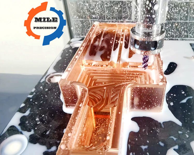
Custom CNC Milling Capabilities
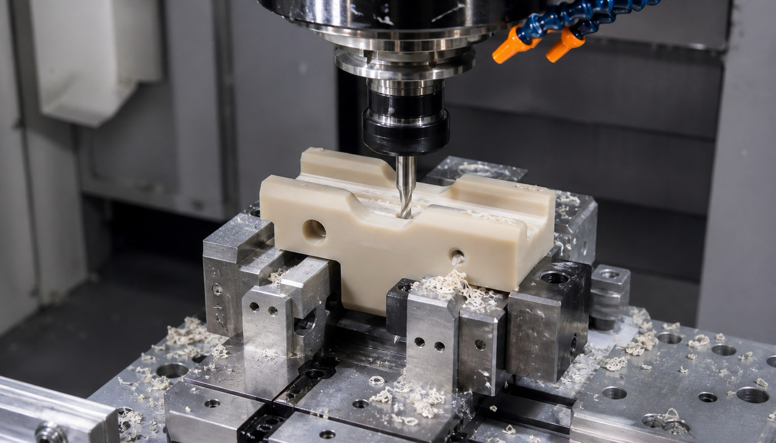
CNC milling uses rotating cutting tools to remove material from solid stock. It is highly flexible for manufacturing flat surfaces, pockets, ribs, bosses, slots, drilled holes, tapped holes, chamfers, contours and complex 3D shapes. CNC milling is often selected when the part is not primarily round, or when a turned part requires secondary milled features.
Compared with manual machining, CNC milling offers repeatability and better control of toolpaths. Compared with molding or die casting, CNC milling avoids tooling cost and is better suited for prototypes, custom parts, engineering validation and low-volume production.
Efficient for plates, pockets, housings, covers, brackets and parts with features accessible from one or several sides.
Useful for side holes, radial features, cylindrical parts and components that need indexed machining around an axis.
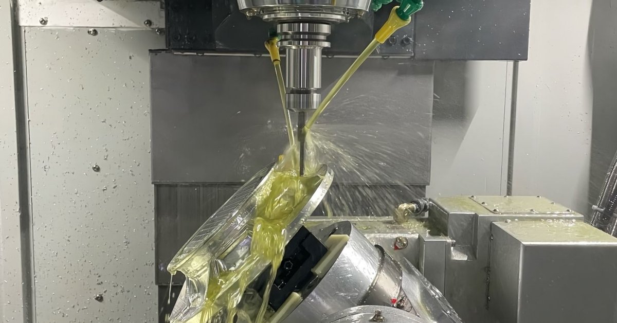
For complex surfaces, angled features, fewer setups and better control of relationships between critical faces.
Drilling, tapping, reaming, boring and countersinking for threaded and precision holes.
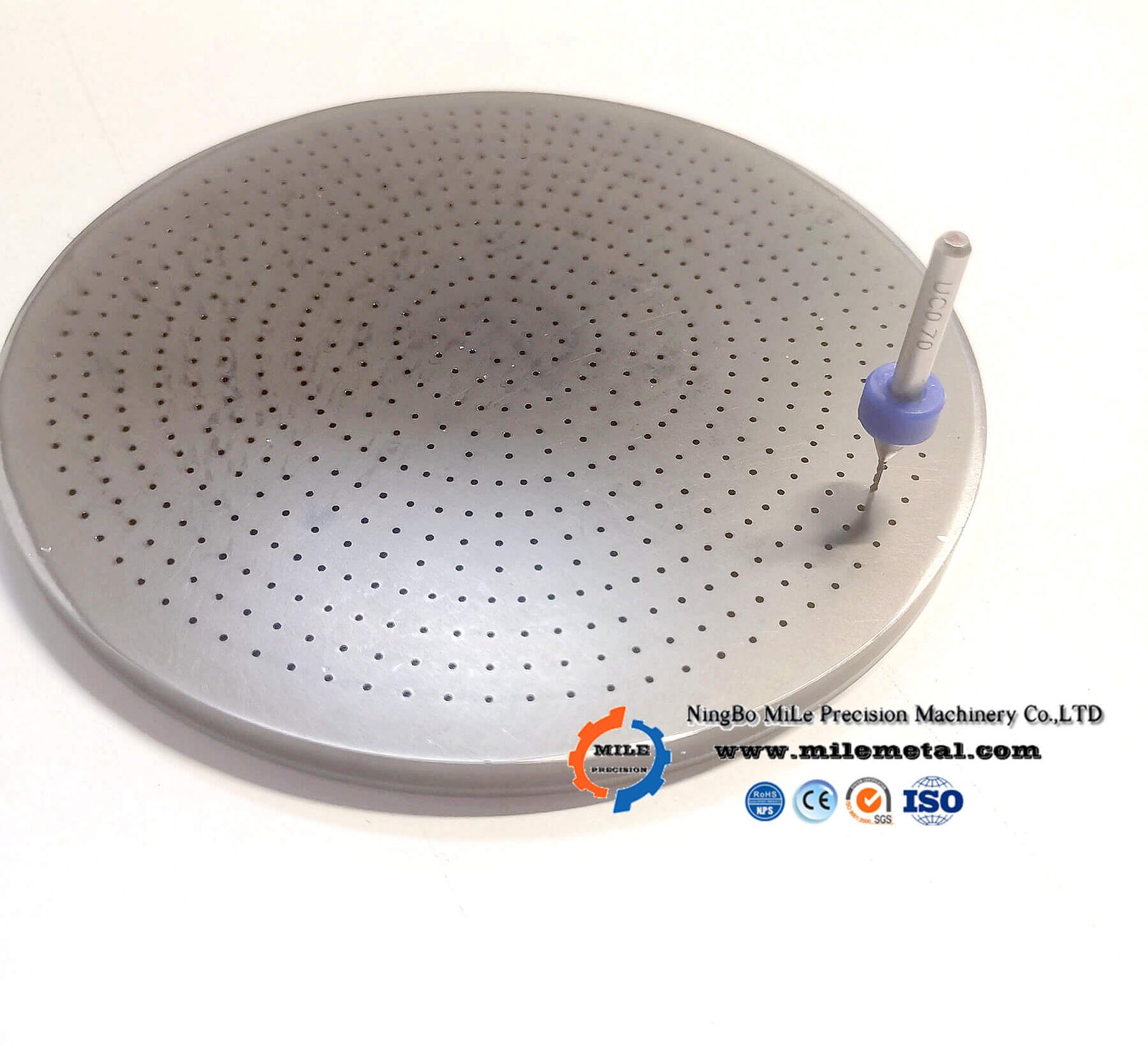
Micro holes, fine grooves, tight pockets and small radii can be reviewed according to material and tool access.
Edge break, polishing, bead blasting, anodizing, plating, passivation, heat treatment and laser marking.
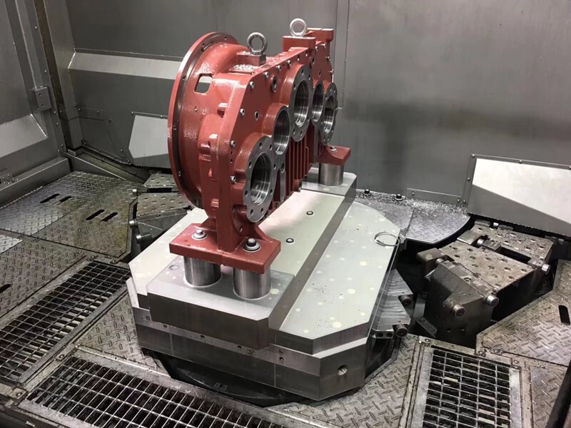
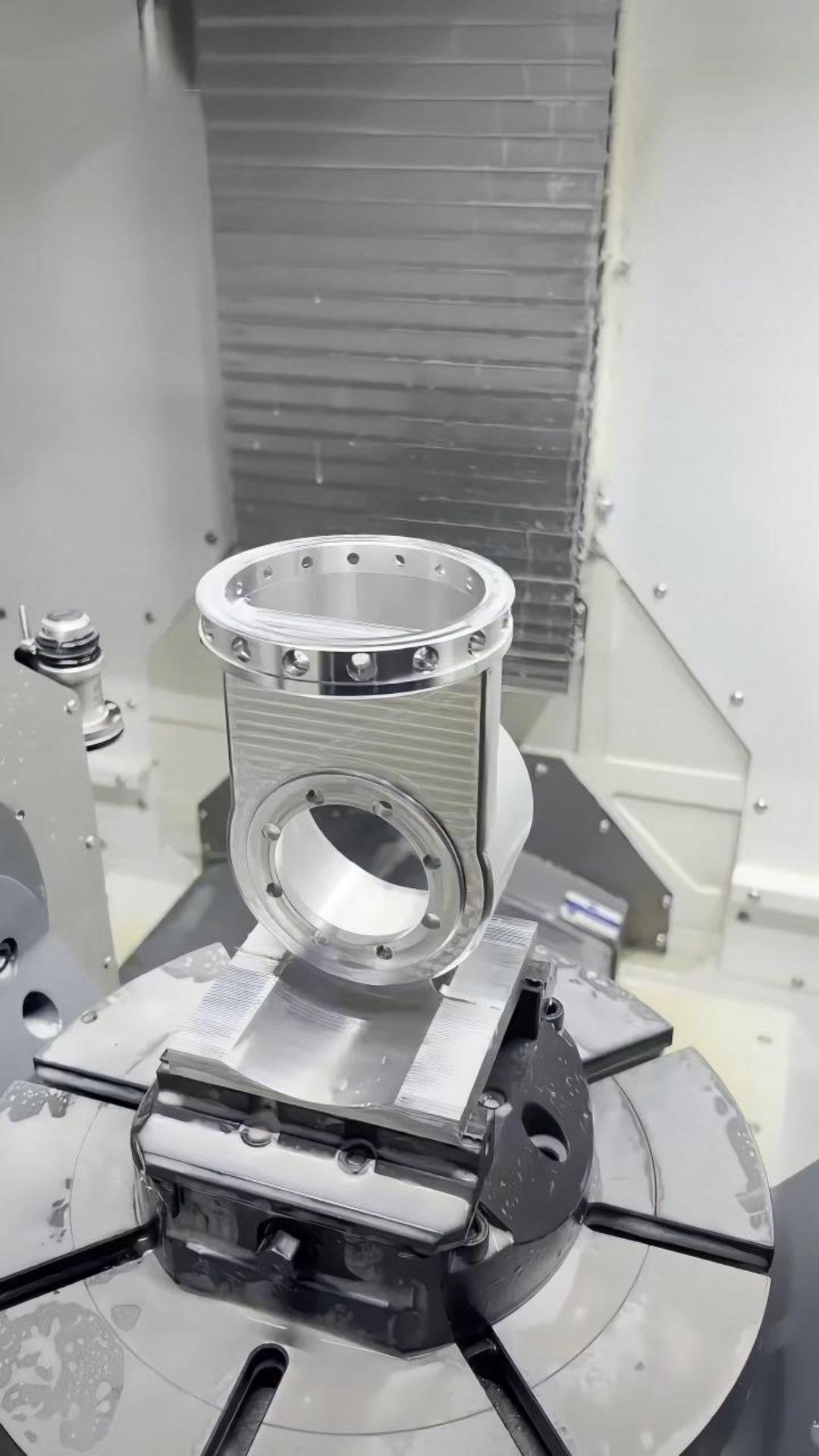
CNC Milled Parts Gallery
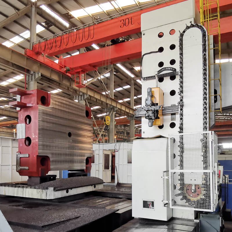
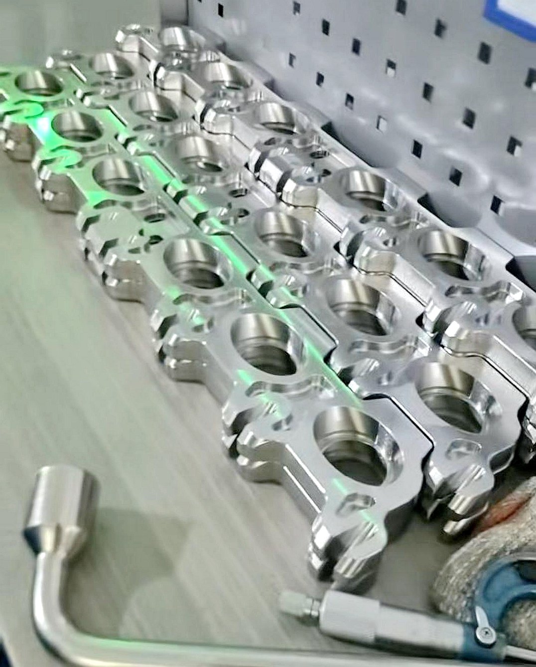
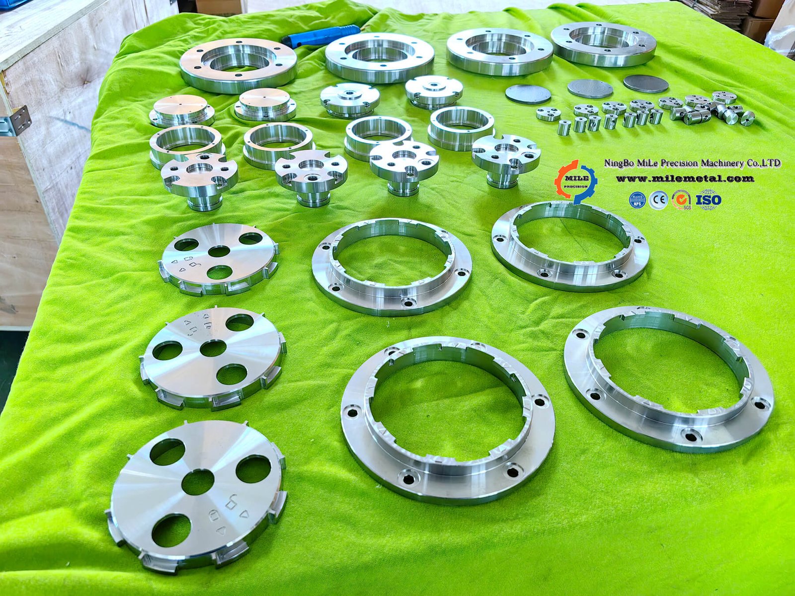
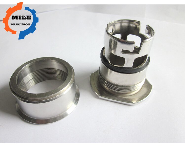
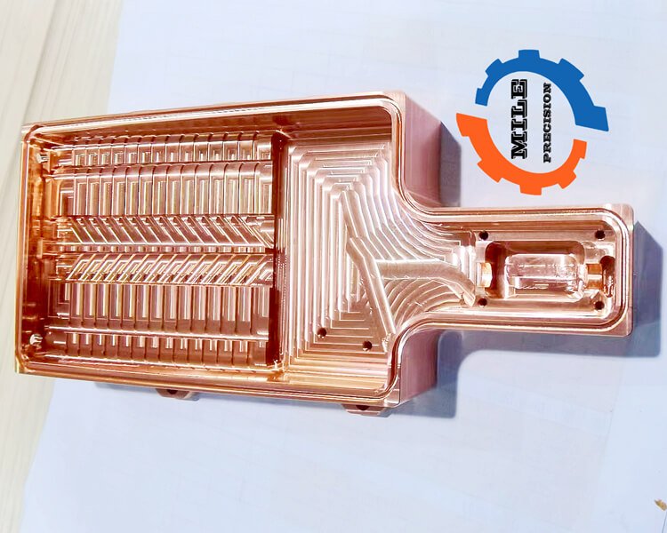
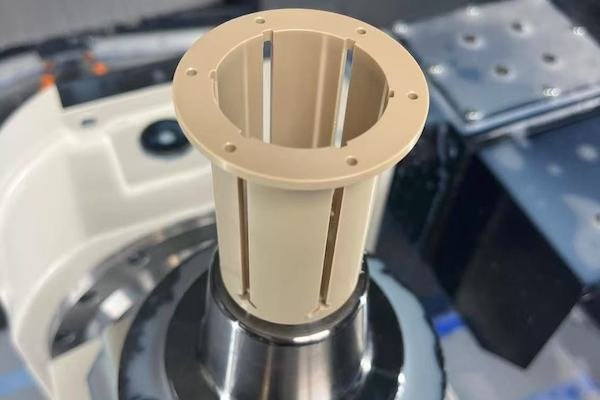
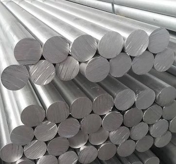
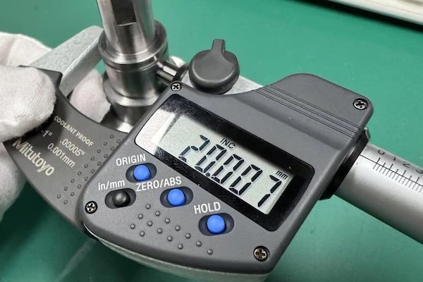
CNC milling is used for many custom parts that need accurate surfaces, holes, mounting faces and assembly interfaces. The gallery below shows typical milled part families and engineering considerations.
CNC Milling Process Flow
File review
Review STEP files, drawings, materials, quantities, tolerances, finish and application requirements.
Fixture and CAM
Plan setups, datum references, clamps, cutters, toolpaths, roughing and finishing passes.
Milling production
Machine faces, pockets, holes, slots, contours, chamfers and threads according to the process plan.
Inspection and finish
Deburr, inspect critical features, apply finishing and package parts for delivery.
CNC Milling Technical Capability Table
| Capability | Typical use | Practical guideline | Design note |
|---|---|---|---|
| Face milling | Flat datum faces, plates, covers and mounting surfaces | Ra 3.2 to Ra 1.6 is common; finer finish needs extra passes | Define flatness only where function requires it |
| Pocket milling | Housings, lightening pockets, cavities and recesses | Depth above 4x tool diameter increases chatter risk | Add internal corner radii and avoid deep sharp square corners |
| Contour milling | Outer profiles, curved shapes and complex edges | Minimum radius depends on cutter diameter and tool reach | Allow larger radii when possible to reduce cost |
| Drilling and tapping | Threaded holes, mounting holes and ports | Thread depth, blind hole depth and bottom clearance must be specified | Use standard thread sizes when possible |
| Boring and reaming | Precision holes, bearing seats and dowel locations | +/-0.01 to +/-0.03 mm possible for selected features | Call out fit class such as H7 when needed |
| 5-axis milling | Angled faces, complex contours and multi-side parts | Reduces setups and improves feature relationships | Best for parts with difficult access or critical geometry |
CNC Milling Materials
Milemetal mills a wide range of metals and engineering plastics. Material selection should consider machinability, strength, weight, corrosion resistance, surface finish, coating response and long-term dimensional stability.
| Material | Common grades | Milling behavior | Typical milled parts |
|---|---|---|---|
| Aluminum | 6061, 6082, 7075, 5052 | Fast to mill, good surface finish and suitable for anodizing | Housings, plates, brackets, heat sinks, optical mounts |
| Stainless steel | 303, 304, 316, 316L, 17-4 PH | Work hardening and heat control require sharp tools and coolant | Manifolds, medical parts, food equipment and corrosion-resistant hardware |
| Carbon / alloy steel | 1018, 1045, 4140, tool steel | Strong and heat treatable, but harder grades increase tool wear | Fixtures, gears, shafts with milled features, wear blocks |
| Brass / bronze | C360, C260, bearing bronze | Generally easy to machine with good finish and low burr risk | Bushings, fittings, connectors, plates and decorative parts |
| Copper | C101, C110, tellurium copper | Ductile and conductive; may need careful chip and burr control | Conductive blocks, heat transfer parts, electrodes and busbars |
| Engineering plastics | POM, nylon, PTFE, PEEK, ABS, PMMA, PC | Low cutting force but sensitive to heat, clamping and moisture | Insulators, fixtures, transparent covers, wear pads and prototypes |
CNC Milling Tolerances and Design Parameters
General CNC milling tolerance depends on material, feature size, wall thickness, tool access, setup count and inspection method. Tight tolerances should be reserved for functional dimensions such as bearing seats, dowel holes, sealing surfaces and assembly interfaces.
| Feature | Typical guideline | Risk factor | Recommendation |
|---|---|---|---|
| General dimensions | +/-0.10 mm is common for many non-critical features | Low | Use a general tolerance standard for normal dimensions |
| Precision holes | +/-0.01 to +/-0.03 mm possible for selected holes | Medium to high | Use reaming, boring or controlled inspection when fit matters |
| Thin walls | Below 0.8-1.0 mm can be unstable depending on material | High | Increase wall thickness or add ribs when possible |
| Deep pockets | Depth greater than 4x tool diameter increases chatter | High | Reduce pocket depth, increase corner radius or split the part |
| Inside corners | Inside radius cannot be smaller than cutter radius | Medium | Use larger radii to lower cost and improve finish |
| Surface finish | Ra 3.2, Ra 1.6 and Ra 0.8 are common engineering targets | Medium | Apply fine finish only to functional or visible surfaces |
Relative CNC Milling Difficulty Chart
This chart compares common materials from a practical milling point of view. Geometry, tolerances and finishing may change the final cost more than material alone.
Design Tips for CNC Milled Parts
Use proper radii
Internal corners need cutter radius. Larger radii reduce tool wear and machining time.
Control pocket depth
Deep pockets need long tools, which can cause chatter, poor finish and tolerance drift.
Strengthen thin walls
Thin walls deflect during cutting and may move after release from the fixture.
Mark critical features
Put tight tolerances only on holes, faces and surfaces that control function.
- Send both STEP files and PDF drawings for accurate quote and manufacturing review.
- Use standard drill sizes and thread sizes when possible.
- Leave access for cutting tools, clamps and inspection probes.
- Consider finishing thickness for anodized, plated or painted parts.
- For cosmetic parts, define visible surfaces and acceptable tool marks.
Surface Finishing Options for CNC Milled Parts
| Finish | Common material | Purpose | Design consideration |
|---|---|---|---|
| As machined | Most metals and plastics | Fastest option with visible tool marks | Define burr removal and edge break expectations |
| Bead blasting | Aluminum, stainless steel | Uniform matte appearance before anodizing or final use | May soften sharp edges and change appearance between batches |
| Anodizing | Aluminum | Corrosion resistance, color and surface protection | Mask critical holes, threads or electrical contact areas if needed |
| Passivation | Stainless steel | Improve corrosion resistance after machining | Use after cleaning and before final packing |
| Electroless nickel | Steel, aluminum, copper alloys | Uniform coating, corrosion resistance and wear performance | Coating thickness affects precision fits |
| Polishing | Aluminum, stainless, brass, copper | Cosmetic surface improvement and lower roughness | Specify visible surfaces and grain direction if important |
Quality Control for CNC Milling
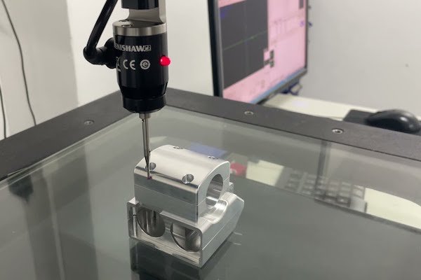
CNC milled parts should be inspected according to the drawing, not only the 3D model. Critical dimensions, datum references, thread quality, surface finish, edge break and coating-sensitive areas should be checked before shipment.
| Inspection item | Common method | When to use |
|---|---|---|
| Hole size and position | CMM, pin gauge, bore gauge | Dowel holes, bearing seats, assembly holes and precision pockets |
| Flatness and parallelism | CMM, height gauge, surface plate | Mounting plates, sealing surfaces and datum faces |
| Threads | Thread plug gauge and visual inspection | Tapped holes, threaded inserts and external thread features |
| Surface finish | Roughness tester and visual inspection | Sealing, sliding and visible cosmetic surfaces |
| Post-finish dimensions | CMM, gauges, micrometers | Anodized, plated or heat-treated precision parts |
Applications of CNC Milling
CNC milling is widely used when parts need accurate geometry, real engineering materials and repeatable production quality. It is practical for one-off prototypes, functional test parts, production fixtures and end-use components.
| Industry | Typical milled parts | Important requirement |
|---|---|---|
| Industrial equipment | Mounting plates, brackets, blocks, guides and fixtures | Flatness, hole position, rigidity and surface protection |
| Fluid systems | Manifolds, valve blocks, fittings and ported housings | Burr-free channels, thread quality, sealing surfaces and pressure integrity |
| Electronics | Heat sinks, housings, frames and connectors | Thermal contact, cosmetic finish, grounding and dimensional stability |
| Medical and laboratory | Instrument components, fixtures and stainless parts | Material traceability, clean surfaces and corrosion resistance |
| Product development | Functional prototypes, test fixtures and pre-production samples | Fast iteration, real material behavior and manufacturable design feedback |
How to Get an Accurate CNC Milling Quote
For a reliable quotation, send clear files and requirements. A STEP model helps CAM programming and geometry review, while a PDF drawing defines tolerances, material, finish, threads and inspection requirements.
3D CAD
STEP, Parasolid or native CAD file for geometry and manufacturability review.
Drawing
PDF drawing with tolerances, threads, surface finish, material and revision.
Quantity
Prototype quantity, production batch size, repeat order expectations and delivery target.
Finish
Anodizing, passivation, plating, polishing, heat treatment, marking and inspection report needs.
Start Your CNC Milling Project
Send your CAD model, drawing, material, quantity and finish requirements. Milemetal can review manufacturability and provide a practical CNC milling quotation.