
Precision Turned Components for the Connector Industry: Materials, Tolerances & Plating
2026-10-15
MILEMETAL ENGINEERING GUIDE · ALUMINUM FINISHING
Type III Anodizing: Hardcoat Thickness, Tolerances & Design Guide
Type III anodizing can improve the wear resistance of an aluminum component, but the coating also changes its dimensions, surface behavior and appearance. A successful specification connects the hardcoat to the part’s function: what slides, what seals, what must fit and what must remain electrically conductive.
1. What Is Type III Hardcoat Anodizing?
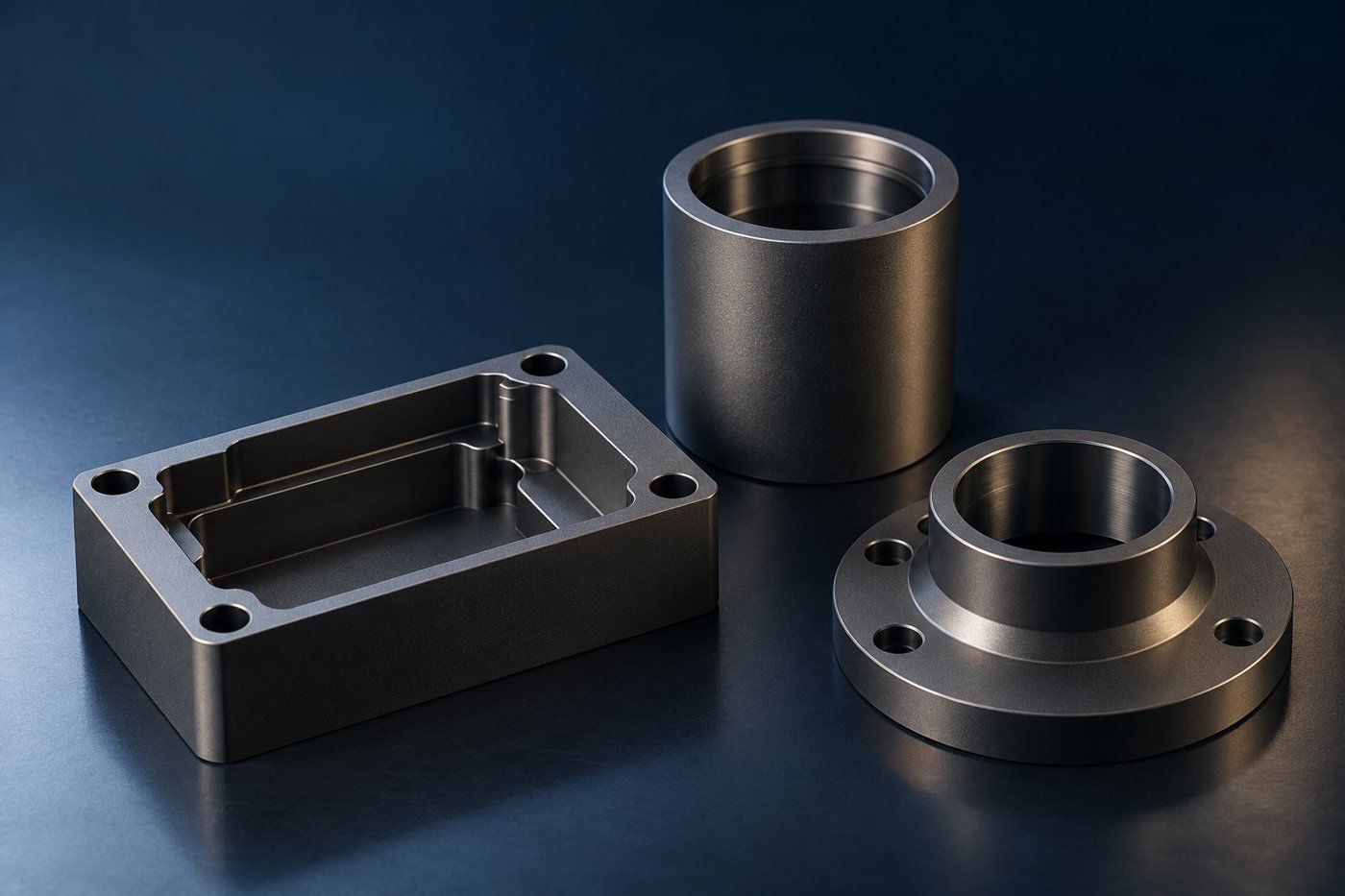
Anodizing is an electrochemical surface-conversion process. Aluminum is made the anode in an electrolyte, and an oxide layer develops at its surface. Unlike an applied paint layer, the anodic coating consumes some of the substrate while also growing outward. The underlying metal still carries the structural load.
Hardcoat is selected when surface wear is a meaningful design concern: a guide face rubbing against a mating component, a sleeve exposed to repeated motion, or an aluminum housing with functional contact surfaces. It is not a universal solution to impact damage, poor lubrication, excessive bearing pressure or an unsuitable base alloy.
The Aluminum Anodizers Council notes that hardcoat performs well in rubbing and sliding applications but can fail under point pressure when the softer aluminum underneath deforms. A hard surface therefore does not make an aluminum part mechanically equivalent to hardened steel. Source: AAC specifying guide.
Type and class describe different requirements
Under MIL-PRF-8625, Type III identifies the hard anodic coating. Class 1 is non-dyed; Class 2 is dyed. Natural coloration is possible in Class 1, so “non-dyed” does not mean colorless. Cite the required specification revision in the purchase documents. The DLA ASSIST record is the official place to check the document’s status.
2. Type III Anodizing Thickness and Specification Parameters
The useful question is not “How thick can hardcoat be?” but “What thickness will meet the functional requirement without creating a fit or geometry problem?” Very thick coatings can increase the challenge of finishing small features and holding a tight assembly tolerance.
| Parameter | Reference | Engineering interpretation |
|---|---|---|
| Broad Type III thickness range | 12.7–115 µm in the AAC reference guide | A reference envelope, not a guaranteed range for every alloy and geometry |
| Default nominal thickness under MIL-PRF-8625F, Amendment 2 | 0.002 in = 50.8 µm, unless otherwise specified | State the intended thickness explicitly instead of relying on a default |
| Default thickness variation under that specification | ±20% up to 0.002 in; ±0.0004 in above 0.002 in, unless otherwise specified | Include coating variation in the finished-size tolerance budget |
| Class | Class 1: non-dyed; Class 2: dyed | Specify color separately where relevant |
| Sealing condition | Defined by functional need and the applicable requirement | Resolve the wear-versus-corrosion tradeoff before ordering |
| Bath temperature, current and time | Controlled by the finishing process | A generic bath recipe does not establish conformity of the finished part |
Thickness references: AAC reference guide; specification values: MIL-PRF-8625F, Amendment 2, §3.7.2.1. These are external references, not a statement of MileMetal’s approved process capability.
Microns, mils and millimeters
A mil is one thousandth of an inch, not one millimeter. A thickness written as 2 mils is 0.002 in, or 50.8 µm. Mixing these units can produce an order-of-magnitude error in a quotation or machining allowance.
| Inches | Mils | Micrometers | Millimeters |
|---|---|---|---|
| 0.0005 | 0.5 | 12.7 µm | 0.0127 |
| 0.0010 | 1.0 | 25.4 µm | 0.0254 |
| 0.0020 | 2.0 | 50.8 µm | 0.0508 |
| 0.0030 | 3.0 | 76.2 µm | 0.0762 |
These conversions do not recommend a thickness. A specific value must be checked against the material, feature size, desired wear behavior and finishing route.
3. Type II vs. Type III: Choose by Function
Type II is often considered for decorative or general protective finishes, while Type III is evaluated for more demanding surface-wear requirements. Do not choose solely by the apparent shade of a sample or assume that a thinner coating has no dimensional effect.
| Design priority | Type II discussion | Type III discussion |
|---|---|---|
| Visible color and cosmetic consistency | Often a starting point for decorative dyed parts | Confirm achievable appearance with representative samples |
| Sliding or abrasive contact | Validate whether the finish is sufficient | Evaluate hardcoat together with mating material and lubrication |
| Close-fitting features | Include even small growth in the tolerance stack | Plan pre-machining allowance or selective masking |
| Corrosion exposure | Specify the complete finish and sealing system | Do not assume thickness alone replaces a sealing decision |
| Electrical contact surfaces | Identify areas requiring conductive contact | Identify areas requiring conductive contact |
| Cost | Compare the complete quoted route | Include masking, testing and dimensional control, not just coating price |
For a broader comparison, see MileMetal’s hard anodizing vs. regular anodizing guide. This article concentrates on specifying and manufacturing Type III parts.
4. Calculate Coating Growth Before Machining
The total oxide thickness is not the same as the outward increase of a surface. The AAC gives an approximate hardcoat planning relationship of 50% penetration and 50% buildup per surface. Actual growth must be agreed with the anodizer for the alloy and process. Source: AAC thickness guide.
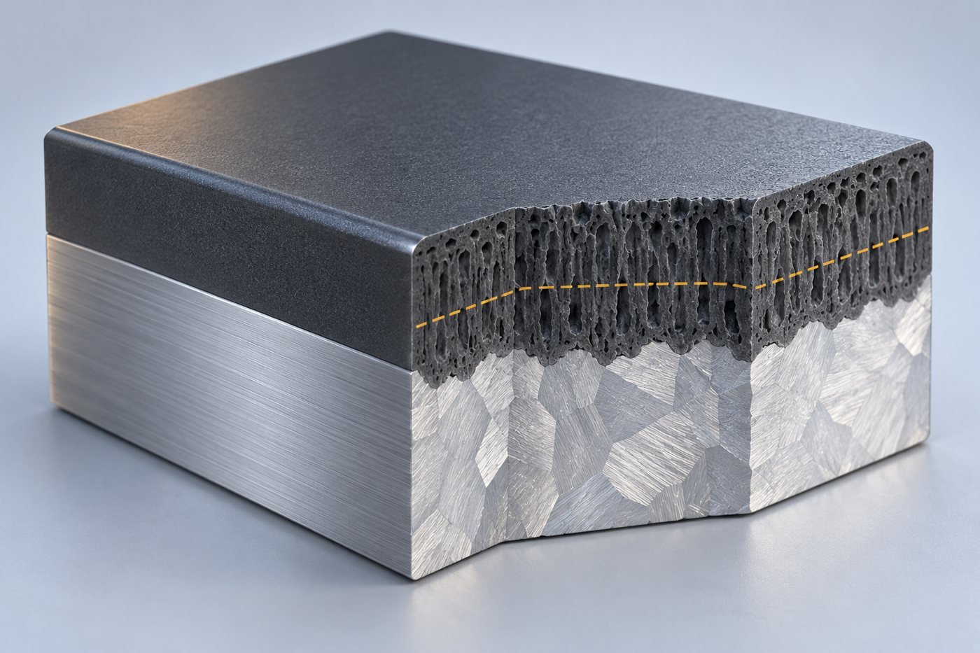
Planning assumption: g ≈ 0.5t
External diameter after anodizing ≈ initial diameter + 2g
Internal diameter after anodizing ≈ initial diameter − 2g
Worked example: a finished 20 mm outside diameter
Assume a design calls for a finished outside diameter of 20.000 mm and a nominal total coating thickness of 50 µm. With 50% outward growth, g is 25 µm, or 0.025 mm. The nominal machining target is therefore:
20.000 − 2 × 0.025 = 19.950 mm before anodizing.
For a bore that must finish at 20.000 mm under the same simplified assumptions, the nominal pre-anodize target is 20.050 mm. The oxide grows into the opening and reduces its size.
Allow for variation, not just the nominal value
Suppose the illustrative coating requirement is 50 ±10 µm. If the growth fraction stays at 50%, the outside-diameter increase ranges from 0.040 to 0.060 mm. A machined shaft at 19.950 ±0.005 mm would then finish between 19.985 and 20.015 mm. That range would not satisfy a finished requirement of 20.000 ±0.010 mm.
Also distinguish dimensions measured on the incoming machined part from those measured on the delivered finished part. Marking a bearing seat “after finish” removes an ambiguity that otherwise travels from the drawing to machining, inspection and assembly.
5. Alloy, Surface Preparation and Color
The alloy and its supplied condition are inputs to the finishing process. Do not replace a specified material with another grade simply because both are described as aluminum. A change that helps machining may alter the finish response or introduce a new qualification requirement.
| Material candidate | What to review | Useful purchasing instruction |
|---|---|---|
| 6061 | Required temper, thickness target and the actual cosmetic acceptance sample | Identify grade and condition on the controlled drawing |
| 7075 | Structural requirements, finish response and fatigue-sensitive features | Approve material and finish as a combined design decision |
| 2xxx alloys | Whether the selected process meets the required wear and coating criteria | Require an alloy-specific review rather than a blanket finish claim |
| Cast aluminum | Composition, porosity, surface condition and consistency across castings | Use representative cast samples for finish approval |
| Mixed lots or welded parts | Whether cosmetic differences or local process differences are acceptable | Define acceptance zones and sample requirements before production |
Machining marks, dents and inconsistent preparation can remain visible after finishing. Anodizing should not be treated as a repair operation for damaged surfaces. Where appearance matters, define the prefinish texture, inspection lighting, viewing distance and approved sample rather than relying on the word “smooth.”
Natural hardcoat coloration varies with alloy and thickness. A dark coating may be dyed, naturally colored, or a different finish entirely. Photographs are useful for communicating shape and appearance, but cannot verify coating type, thickness or wear performance.
6. Decide Sealing, Masking and Rack Contact Locations
When wear resistance dominates
MIL-PRF-8625F §3.8.2 specifies unsealed Type III when maximum abrasion or wear resistance is the principal function. Confirm the full requirement before adding a sealing step.
When corrosion exposure dominates
The same section calls for sealing to be specified for exterior, non-maintained applications that need corrosion resistance and can accept reduced abrasion resistance. The complete finishing system must match the service conditions.
Source: MIL-PRF-8625F, Amendment 2, §3.8.2. Agree on the accepted sealing treatment and any application-specific restrictions with the finishing supplier.
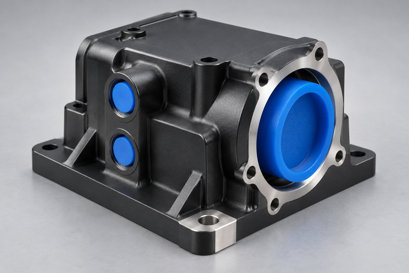
Masking is especially important where the assembly needs electrical continuity, a close fit or a controlled thread. Identify those surfaces on a marked drawing. “Mask as required” shifts a design decision to the process operator and may produce a part that looks correct but cannot be assembled.
- Grounding lands: identify the contact area and its required protection or conductivity condition.
- Bearing seats and precision bores: state whether they are coated, masked or finished by an approved subsequent operation.
- Threads: specify the finished gauging requirement and review coating access and buildup.
- Rack contact zones: agree where process contact marks may remain.
- Mask boundaries: define where the transition can occur so it does not cross a sealing or sliding surface.
A threaded insert, mixed-metal assembly or trapped recess can complicate processing. Review the assembly sequence before committing to a finished-part drawing. Rework after anodizing may expose aluminum and require a separate engineering disposition.
7. Product Geometry Examples from the MileMetal Library
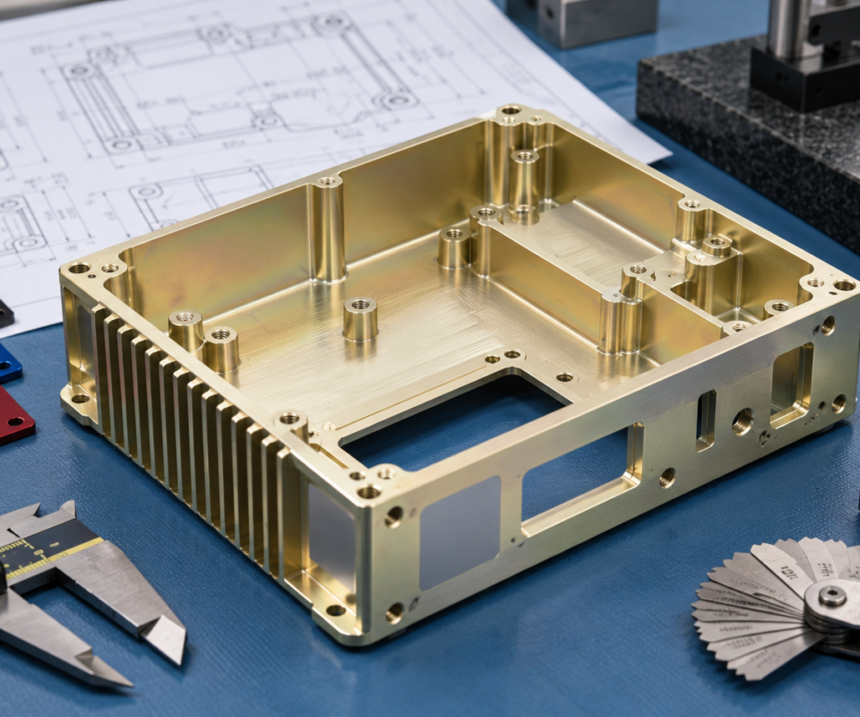
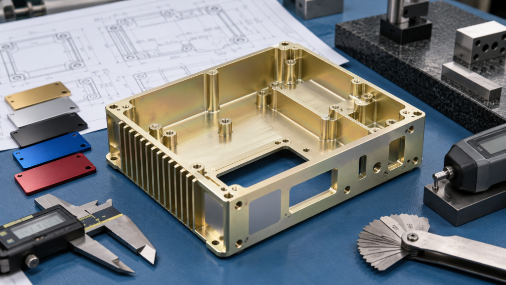
These six existing MileMetal product images show relevant CNC aluminum geometries: housings, pockets, ports, mounting faces and precision bores. They are presented as design examples; the photographs do not certify that every pictured part received Type III anodizing.
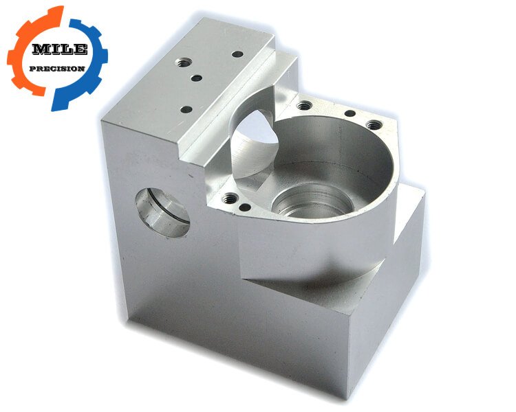
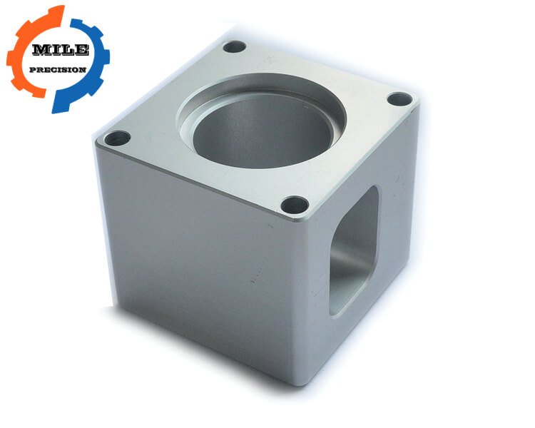


Use the gallery to identify the surfaces that matter on your own part. A housing may need a cosmetic exterior, a controlled bearing bore and an electrically conductive mounting land—all within the same component. Those requirements should be separated on the drawing rather than covered by one general finish note.
8. Inspect the Coating and the Finished Component
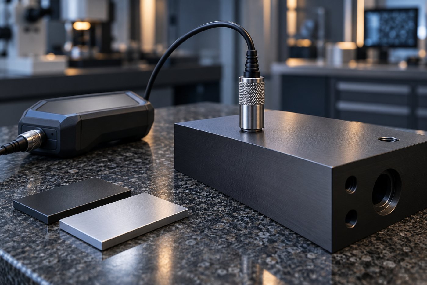
Thickness is only one acceptance characteristic. A part can have the correct coating reading on an accessible face and still fail at a bore, thread, masked interface or wear surface. Agree on measurement locations and the final inspection stage before production starts.
| Characteristic | Possible method | What must be agreed |
|---|---|---|
| Coating thickness | Calibrated eddy-current measurement; sectioning where specified | Locations, probe suitability, limits and treatment of inaccessible areas |
| Finished dimensions | Suitable dimensional gauges and thread gauges | Post-finish limits, datum setup and sampling |
| Appearance and defects | Visual inspection against approved criteria | Lighting, zones, sample and allowable rack marks |
| Wear performance | The test required by the invoked specification | Alloy, specimen, sealing condition and acceptance criterion |
| Corrosion or sealing performance | The test required for the agreed finish system | Test conditions and limits; no unsupported service-life conversion |
| Electrical contact areas | Mask-boundary inspection and application-specific continuity check | Contact area, surface condition and assembly requirement |
A hardness number without its method, load, specimen and coating condition is weak evidence for a functional claim. For a wear-critical component, request the relevant wear test rather than assuming that a quoted hardness guarantees service life. Likewise, laboratory corrosion exposure does not translate directly into years of field performance.
Problems to address before repeat production
- Interference after finishing: check pre-machining allowance and coating variation before changing the mating part.
- Different shades between lots: check material traceability and the agreed preparation and color criteria.
- Patchy or damaged surfaces: review incoming condition, cleaning, racking and process control with the finisher.
- Unexpected contact marks: move approved rack zones away from functional or prominent cosmetic surfaces.
- Poor fit in internal features: inspect the actual feature; an external-face thickness reading does not prove internal coverage.
9. Put the Complete Requirement on the Drawing
A useful finish note must tell the supplier what result is required and how that result will be accepted. Keep the finished drawing as the contractual reference, with any supplier machining allowances recorded separately and controlled.
ILLUSTRATIVE DRAWING NOTE — ENGINEERING REVIEW REQUIRED
Hard anodize to MIL-PRF-8625F, Amendment 2, Type III, Class 1.
Total coating thickness: 50 ±10 µm on designated surfaces.
Unsealed for the specified wear application.
Mask areas identified M1–M3; rack contact permitted only in zone R1.
Critical dimensions identified F1–F4 apply after finishing.
Inspect thickness at locations T1–T3 and provide the agreed report.
This example is not a universal specification. In particular, the illustrative 50 ±10 µm requirement may be incompatible with a tight fit unless the dimensional stack is reviewed. Replace all zone references with actual drawing details, and use the sealing condition and specification revision required by the application.
Send a quotation package that can be reviewed
- Part definition: drawing revision, PDF and available STEP file.
- Material: alloy, temper, product form and substitution rules.
- Finish: specification, type, class, thickness, color and sealing.
- Functional surfaces: finished fits, masked zones, electrical contacts and wear faces.
- Acceptance: thickness locations, visual criteria, test reports and traceability.
- Order scope: sample quantity, production quantity, repeat demand, packaging and requested date.
Compare quotations on that same basis. More masking, tighter finished tolerances and additional test documentation can change cost even when the overall part size remains unchanged. If the geometry or alloy changes after first-article approval, review the finishing assumptions again.
Planning a Hard-Anodized Aluminum Part?
Send MileMetal your drawing, alloy, quantity and finishing requirements. Request a coordinated review of machining allowances, masking and inspection before production.
10. Frequently Asked Questions
Is Type III anodizing the same as hard anodizing?
Type III is commonly called hardcoat or hard anodizing. “Type 3” and “type three” are alternative spellings used in searches; the drawing should use the designation required by the specified standard.
Is all black anodizing Type III?
No. Black color does not establish the anodizing type. Request the process designation, thickness and relevant acceptance records, not just a black sample.
Does a 50 µm coating add 100 µm to a shaft diameter?
Not under the approximate 50% outward-growth assumption used in this guide. A 50 µm total oxide layer would add roughly 25 µm per surface, or 50 µm to the diameter. Confirm the actual process allowance before machining.
Should Type III hardcoat always be sealed?
No. The sealing choice depends on the wear and corrosion requirements and the governing specification. State the required condition explicitly rather than leaving it to interpretation.
Can hardcoat fix scratches or machining defects?
Do not rely on it to hide defects. Control the incoming surface and agree on prefinish preparation and visual acceptance before coating.
Can I use Type III on a precision bore or thread?
Potentially, but coating access, dimensional change and gauging need review. Specify which features receive coating and which require masking or another approved approach.
Technical Sources and Related Guides
Specification status checked on October 22, 2026. Always use the revision invoked by the drawing or contract. Reference ranges and calculations here do not constitute a MileMetal capability guarantee.
- DLA ASSIST: MIL-PRF-8625 document record
- MIL-PRF-8625F, Amendment 2: full specification copy
- Aluminum Anodizers Council: anodizing reference guide
- Aluminum Anodizers Council: specifying anodized aluminum
- MileMetal: hard anodizing versus regular anodizing
- MileMetal: preparing CAD files for machining
- More MileMetal manufacturing guides