Custom Aluminum Enclosure CNC Machining: Design, Materials, Tolerances and Finishing Guide
2026-10-13
Type III Anodizing: Hardcoat Thickness, Tolerances & Design Guide
2026-10-22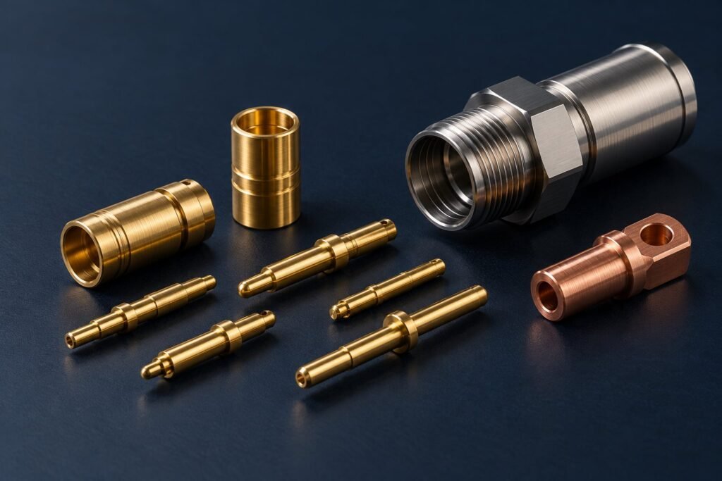
MileMetal / Manufacturing insights / Connector components
Precision Turned Components for the Connector Industry: Materials, Tolerances & Plating
A connector can contain an accurately machined pin and still fail to mate, overheat or lose electrical continuity. Reliable performance depends on how the contact material, finished dimensions, surface condition and assembly work together. This guide explains what engineers and buyers should specify when sourcing precision turned components for the connector industry.
1. Which Connector Parts Are Made by CNC Turning?
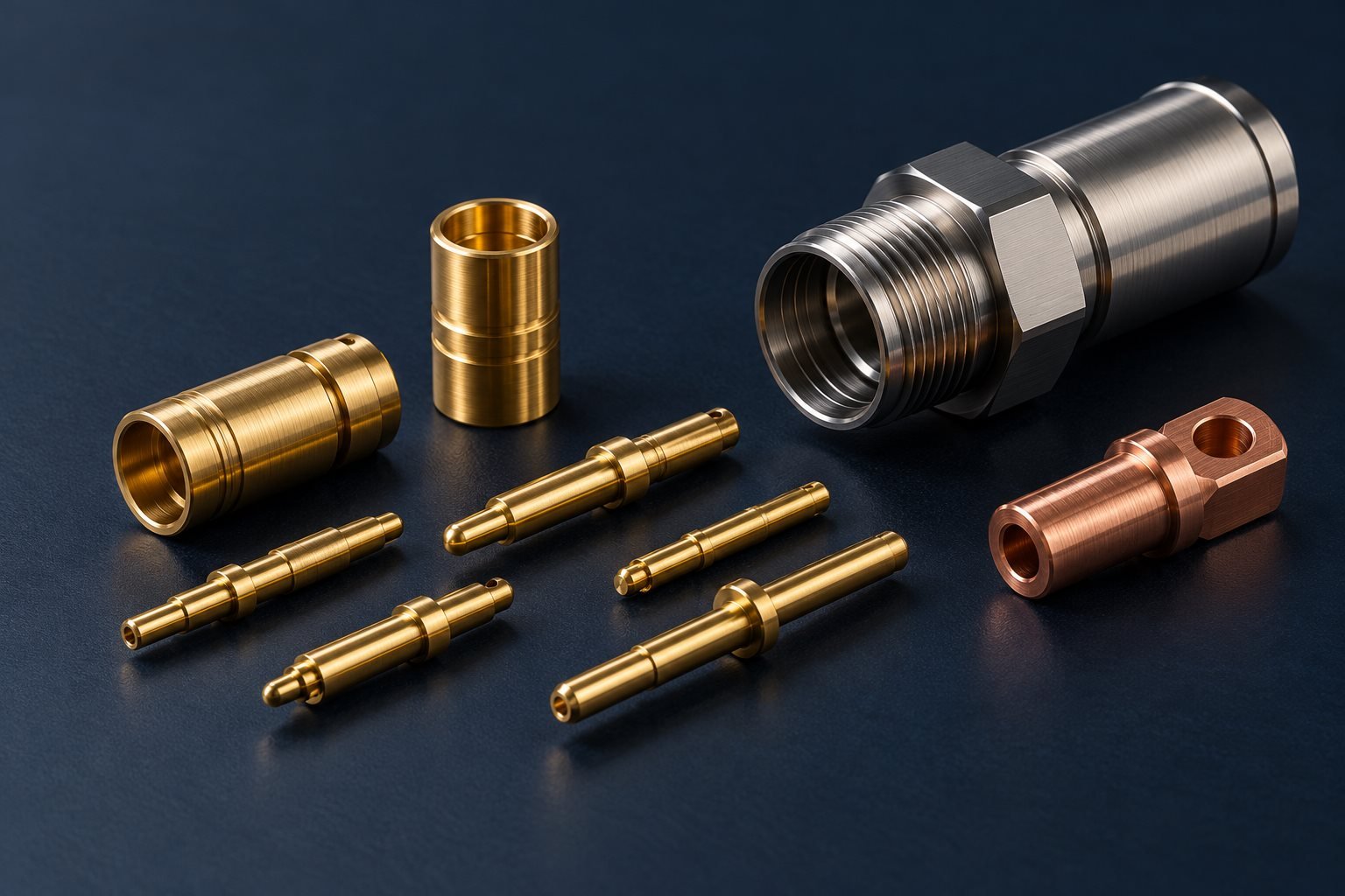
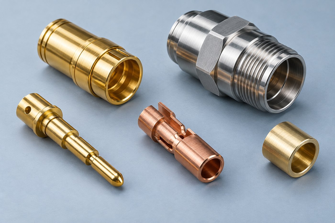
Turning is a useful starting point when a part’s function depends on a common axis. A contact pin may combine a mating tip, a locating shoulder and a termination end in one piece. A shell may need an internal bore aligned with an external thread. These relationships matter more than the visual complexity of the part.
| Component | Purpose | Features to control |
|---|---|---|
| Male contact pin | Provides the mating electrical interface | Finished contact diameter, tip profile, straightness and surface condition |
| Socket body or receptacle shell | Locates a mating pin or a separate spring contact | Bore size, entry geometry, wall thickness and retention features |
| Crimp or solder terminal | Connects the contact to a conductor | Wire cavity, termination geometry, wall thickness and cleanliness |
| Threaded housing or coupling part | Locates and secures the connector assembly | Thread specification, datum alignment, sealing faces and locking details |
| Sleeve, spacer or insert | Controls position or supports assembly | Length stack, press-fit diameter, lead-in and burr limits |
A turned socket shell is not automatically a spring contact. Some receptacles use a separate stamped contact inside the shell; others use a slotted contact element. Specify which part supplies the contact force before choosing its alloy, temper and manufacturing sequence.
2. Choosing Materials for Turned Connector Components
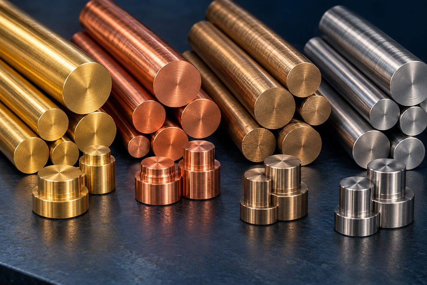
Separate current-carrying contacts from structural hardware during material selection. Brass is widely used for machinable connector parts; copper supports high-conductivity contacts; spring copper alloys serve resilient contact elements; stainless steel is useful for durable housings. The correct choice depends on the part’s function, not simply its appearance. Amphenol RF’s material guide explains these functional differences.
| Material candidate | Design question | Information to put on the drawing |
|---|---|---|
| Free-machining brass, such as C36000 | Does the specified alloy meet the electrical, mechanical and substance requirements? | Exact alloy, product form, temper and required material declaration |
| Tellurium copper, C14500 | Is high conductivity needed together with substantial machining? | Material standard, temper and any conductivity acceptance requirement |
| Spring copper alloy | Must the part recover elastically after repeated mating? | Alloy, final condition, heat treatment if applicable and force requirements |
| Stainless steel housing material | Which environmental exposure and mechanical loads govern selection? | Grade, surface treatment, sealing requirements and thread details |
For a numerical reference, the Copper Development Association lists C14500 electrical conductivity as 93% IACS at 68°F (20°C). IACS is a conductivity reference scale; it is not a connector current rating. The alloy data does not establish the temperature rise, allowable current or durability of an assembled contact. Source: CDA C14500 alloy data.
Do not approve a material substitution solely because two grades share a familiar trade name. Compare the actual composition, supplied condition and required performance. If the customer specifies a lead-free material, identify the approved grade explicitly instead of allowing an unspecified brass substitution.
3. Define the Dimensions That Control Connector Performance
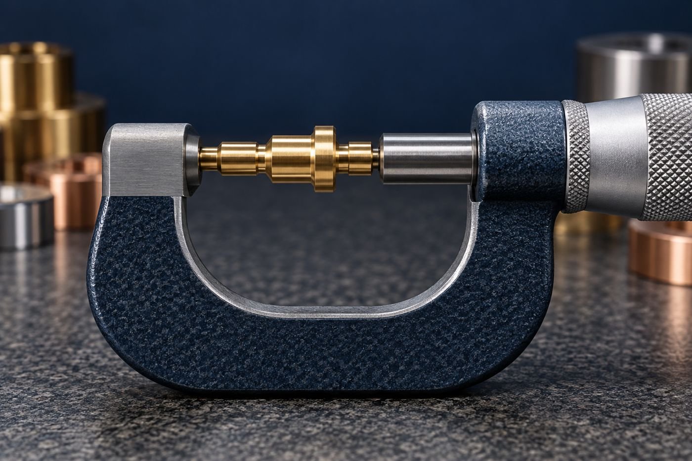
Start with the mating interface and work backward to the manufacturing drawing. Identify the contact diameter, insertion depth, locating shoulder, retention feature and relevant datum axis. Apply tight tolerances to the features that influence function, and allow practical tolerances elsewhere.
| Characteristic | Example callout | What to clarify |
|---|---|---|
| Finished mating diameter | Ø2.000 ±0.010 | Measured after all coating operations; identify the contact land |
| Shoulder-to-tip length | 12.00 ±0.05 | Define the functional shoulder and measurement endpoint |
| Contact surface roughness | Ra ≤0.8 µm | Identify the surface, measurement stage, direction and evaluation conditions |
| Contact-land circular runout | 0.02 relative to datum axis A | Define the datum feature and verification setup |
| Assembly lead-in | 0.20 × 45° chamfer | Check engagement length and permissible edge rounding |
| Finished external thread | M6 × 0.75–6g | Confirm mating thread, coating allowance and finished gauging condition |
One diameter tolerance does not control every geometric error. A shaft can satisfy a size requirement while a different feature is misaligned. Use a consistent drawing standard and define appropriate geometric controls where the assembly needs them. Also avoid applying a generic roughness requirement to every surface when only a short mating land needs a fine finish.
Electrical contact interface
Review contact diameter, alignment, wipe distance, surface condition and normal force together. Electrical continuity depends on the assembled interface, not just the machined part.
Mechanical assembly interface
Review retention shoulders, press fits, threads and sealing lands. Include the mating component’s tolerances in the stack before tightening one part’s drawing.
4. Plating Changes Both Surface Performance and Fit
Gold over nickel, tin and silver are possible connector finishes with different application tradeoffs. Gold is used for corrosion-resistant contact surfaces; tin supports economical solderable interfaces; silver offers low resistivity but can tarnish. Finish selection must match the mating system. See Amphenol RF’s finish comparison.
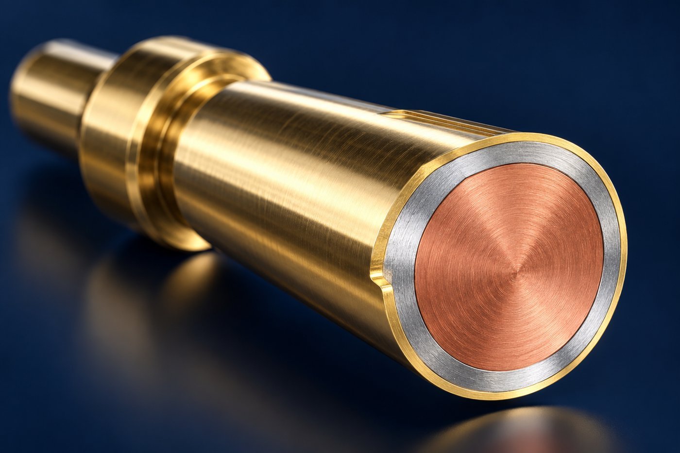
Published products illustrate why a drawing must state a thickness rather than simply say “gold plated.” One Mill-Max catalog sheet lists gold-over-nickel options of 0.25 µm and 0.76 µm. These are product-specific options, not universal thickness recommendations for custom contacts.
A worked example: diameter growth after plating
For a uniformly coated cylindrical surface, let t be the total coating thickness on one side, including all deposited layers. External diameter increases by approximately 2t; an internal bore decreases by approximately 2t if the coating reaches both opposing surfaces at that thickness.
Internal bore after plating ≈ machined bore − 2t
Suppose an illustrative pin needs a finished diameter of 2.000 mm, and its nominal combined coating is 3 µm per side. The nominal starting diameter is 2.000 − (2 × 0.003) = 1.994 mm.
Now assume coating thickness can range from 2 to 4 µm per side. That alone changes the diameter addition from 0.004 to 0.008 mm. If machining is 1.994 ±0.005 mm, the simplified worst-case finished range becomes 1.993–2.007 mm. This fits the illustrative 1.990–2.010 mm limits, but the calculation still assumes uniform coverage and excludes shape error and measurement uncertainty.
Actual deposition may differ at edges, blind holes and recesses. Agree on minimum local thickness, measurement locations, any maximum thickness needed for fit, and whether selective plating or masking is necessary. A nominal average thickness is insufficient when a small bore or close fit controls acceptance.
5. Manufacturing Route and Design for Machining
Drawing revision, material, datum system and coating stack.
Turn, drill and add specified secondary features.
Deburr, clean, heat treat if required and apply the specified finish.
Check finished characteristics and protect parts for shipment.
The sequence must be adapted to the material and part. For example, heat treatment may require allowance for distortion and additional finishing. Secondary slotting or cross-drilling may introduce burrs after the main turning operation, so inspection must address the final condition.
When is Swiss-type turning worth considering?
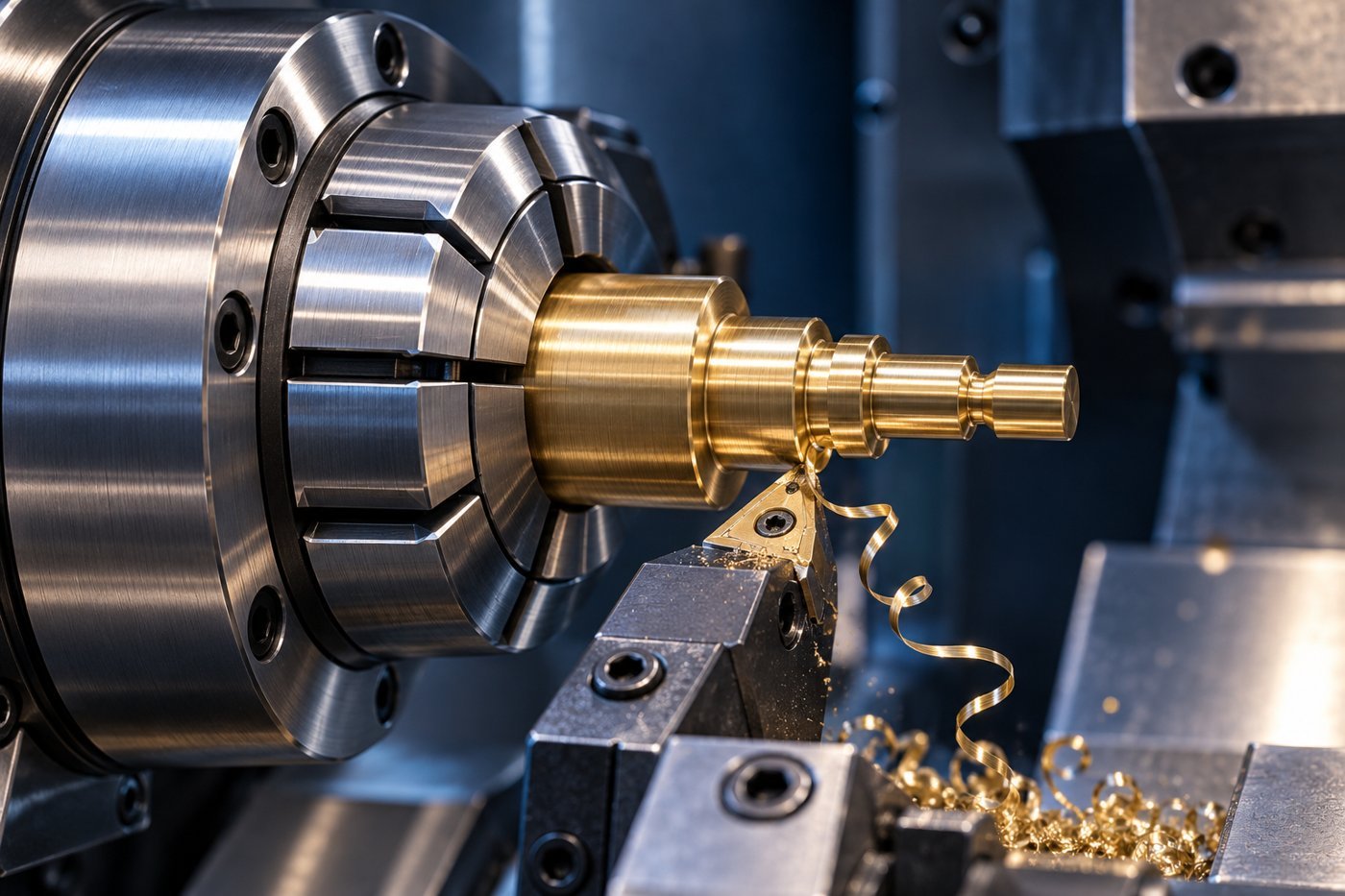
For long, slender pins, support close to the cutting zone can help control deflection. Swiss-type turning is therefore worth evaluating for suitable geometries and volumes. Short, rigid connector bodies may suit a conventional turning center. Machine selection should follow the part’s support requirements, secondary operations, stock availability and economics.
- Keep datum relationships practical. Where possible, make important coaxial features in one setup.
- Review small internal features early. Deep narrow bores affect tool access, chip removal, cleaning and inspection.
- Define edges by function. An uncontrolled edge break can shorten a contact land or alter retention.
- Account for thin walls. Clamping and deburring can distort delicate socket shells.
- Protect termination features. Burrs or residue inside a wire cavity can compromise the next assembly operation.
For related process planning, read MileMetal’s Swiss-type CNC machining design guide and CAD file preparation guide.
6. Inspection: Verify the Part and Validate the Assembly
A dimensional report demonstrates conformity to measured drawing characteristics. It does not by itself demonstrate a connector’s current rating, contact resistance or mating life. Separate component acceptance from assembled-product validation, and agree on who performs each test.
| Control point | Possible verification method | Acceptance basis |
|---|---|---|
| Material identity and condition | Supplier material records and agreed incoming checks | Specified alloy, condition and purchase requirements |
| Contact diameters and lengths | Suitable micrometers, optical measurement or other validated gauges | Drawing limits at the stated manufacturing stage |
| Bores and threads | Appropriate plug gauges, thread gauges and dimensional measurement | Finished feature specification |
| Burrs and surface damage | Visual inspection at agreed magnification and accessibility | Defined critical zones and defect criteria |
| Coating thickness | Validated X-ray fluorescence or another suitable coating method | Layer requirements and identified measurement locations |
| Contact resistance and temperature rise | Controlled electrical tests on representative assemblies | Connector design specification and agreed test conditions |
| Mating durability and retention | Cycle testing and force measurement | Application-specific mechanical and electrical limits |
Choose measurement equipment with suitable resolution, uncertainty and access to the feature. Agree on sampling, lot identification and report requirements before production. Where process capability data is requested, define the characteristic and production conditions; a capability index is not meaningful evidence for a different material, setup or geometry.
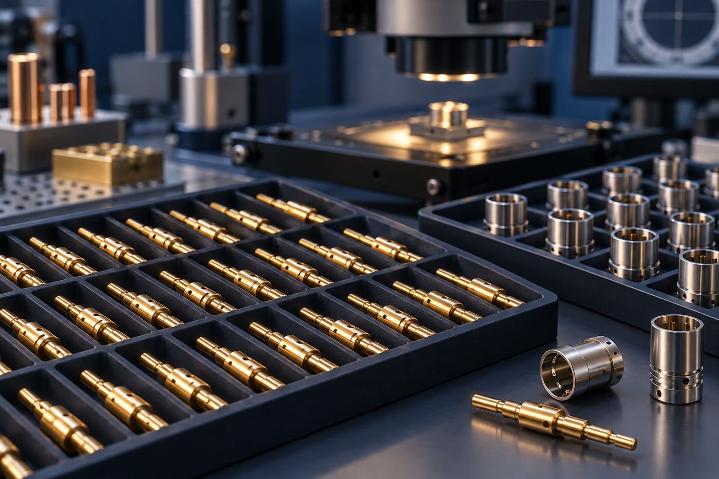
Packaging is part of the control plan. Small pins can bend, and finished contact surfaces can be damaged when loose parts rub together. Specify trays, separators or other protection where bulk packing could change the delivered condition.
7. What Drives the Cost of Custom Turned Connector Parts?
The lowest unit machining price may not produce the lowest accepted-part cost. A useful comparison includes stock, setup, cycle time, finishing, inspection, expected yield and protective packaging. Ask suppliers to quote against the same drawing revision, material, finish and delivery quantity.
Very tight nonfunctional tolerances, deep narrow holes and unnecessary surface-finish requirements can add work without improving the connector. Selective precious-metal plating may reduce coated area, but masking and handling also cost money. Compare complete process routes rather than assuming one choice is always cheaper.
Use prototypes to resolve fit and functional questions, then confirm how production parts will be made. A prototype produced with a different material condition or coating stack should not be treated as conclusive evidence for the final version. Request a fresh review whenever a design change affects contact geometry or finish.
8. RFQ Checklist for a Connector Components Manufacturer
A complete request for quotation reduces assumptions and makes competing offers easier to compare. Send the following information with your inquiry:
- Controlled files: a dimensioned PDF drawing, revision number and available STEP model.
- Material: exact grade, temper or condition, and acceptable substitutions if any.
- Functional interfaces: mating component details, datum features and critical characteristics.
- Coating: layer sequence, thickness requirements, coverage areas and finished-size requirements.
- Assembly requirements: termination method, retention features, cleanliness and packaging.
- Validation requirements: electrical and mechanical tests, acceptance criteria and responsibility.
- Commercial quantities: prototype quantity, batch size, forecast demand and requested delivery date.
- Documentation: material records, dimensional reports, coating records and traceability needs.
Discuss Your Connector Component Drawing with MileMetal
Send your contact pin, socket body, terminal or connector housing drawing with the material, coating and quantity requirements. Ask MileMetal to review manufacturability and confirm the project-specific production and inspection scope.
9. Frequently Asked Questions
What is the best material for precision turned connector components?
There is no single best material for all connector parts. Choose by function: conductivity for a current path, elastic behavior for a spring contact, or mechanical and environmental performance for a housing. Specify the exact alloy and condition before comparing quotations.
Should contact dimensions be specified before or after plating?
Dimensions that control final mating should have a clearly defined finished condition. Manufacturing documents may also need pre-plating targets, but those targets must account for the complete coating stack and its variation.
Does a tighter machining tolerance guarantee lower contact resistance?
No. Size control supports fit, but resistance also depends on material, contact force, surface condition, contamination and the mating system. Validate electrical performance on representative assemblies under defined conditions.
Are machined contacts always better than stamped contacts?
No. Turning is suitable for cylindrical features and certain robust contact designs. Stamping and forming can suit resilient geometries and production requirements. Compare the assembled function and total manufacturing route.
Can the same coating be used for every connector application?
No. The mating finish, environment, termination process and required durability influence selection. State the coating stack and test requirements instead of choosing by color or appearance.
What determines the lead time for a custom connector part?
Material availability, setup, secondary operations, outsourced finishing, inspection and order volume all affect delivery. Request a project-specific schedule that includes first-article review and final finishing.
10. Technical References & Further Reading
Material data and commercial coating examples support the discussion; they do not establish MileMetal’s manufacturing limits. Numerical drawing and fit examples in this article are illustrative calculations.