
Laser Marking vs Engraving vs Etching: A Practical Guide for CNC Parts
2026-06-19
8 Major CNC Machining Defects Analysis: Causes, Solutions and Prevention
2026-09-16
5 Electroplating Defects Analysis: Causes, Diagnosis and Prevention for Metal Parts
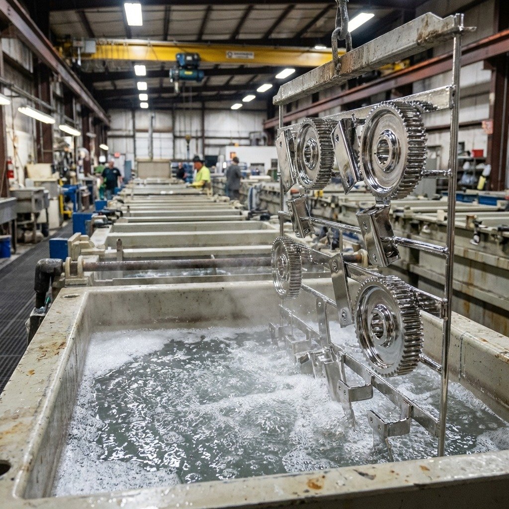
This 5 electroplating defects analysis explains peeling, pitting, burning, skip plating and color variation. These defects are not only cosmetic problems; they can point to poor adhesion, unstable current density, bath contamination, weak pretreatment or geometry-related coverage issues. For OEM metal parts, the correct response is not simply to replate the batch. The process root cause must be found and controlled.
Why the Same Electroplating Defect Keeps Coming Back
In production, one common mistake is to treat an appearance defect as a single bad part. A batch is stripped, replated, visually improved and released. A few days later, the same defect appears again because the real variable was never identified. Electroplating is sensitive to many linked factors: base material quality, surface cleaning, activation, current density, rack contact, anode layout, bath chemistry, filtration, agitation, rinse quality, drying and post-treatment.
A stable plating process therefore needs two kinds of information. First, the visible defect must be named accurately. Second, the defect must be compared against process layers such as part location, rack position, shift, material batch, current setting and bath condition. When this data is recorded, patterns become easier to see.
Do not stop at appearance
Appearance is the starting point, not the conclusion. Peeling may point to weak pretreatment, but it can also be related to base metal oxidation, long transfer time after activation, poor cleaning or mechanical stress after plating. Pitting may come from the substrate, trapped contamination, particles in solution or gas bubbles.
The best investigation separates the defect by position, time and process condition. If defects concentrate near edges, holes or sharp corners, current distribution should be reviewed. If defects follow one material batch, the substrate surface and pretreatment match should be checked. If defects increase later in the bath cycle, filtration, contamination and chemistry maintenance become stronger suspects.
Five Common Electroplating Appearance Defects
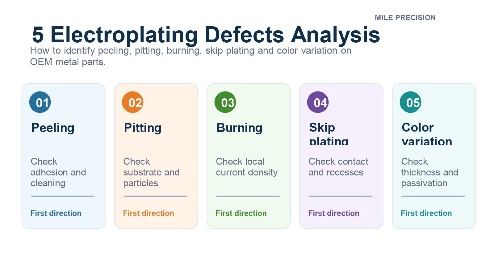
The following defect types are frequently seen on plated metal components. The names may look simple, but each defect can have several possible causes. For precision parts, it is important to connect visual symptoms with functional risks such as corrosion, contact resistance, wear performance and coating life.
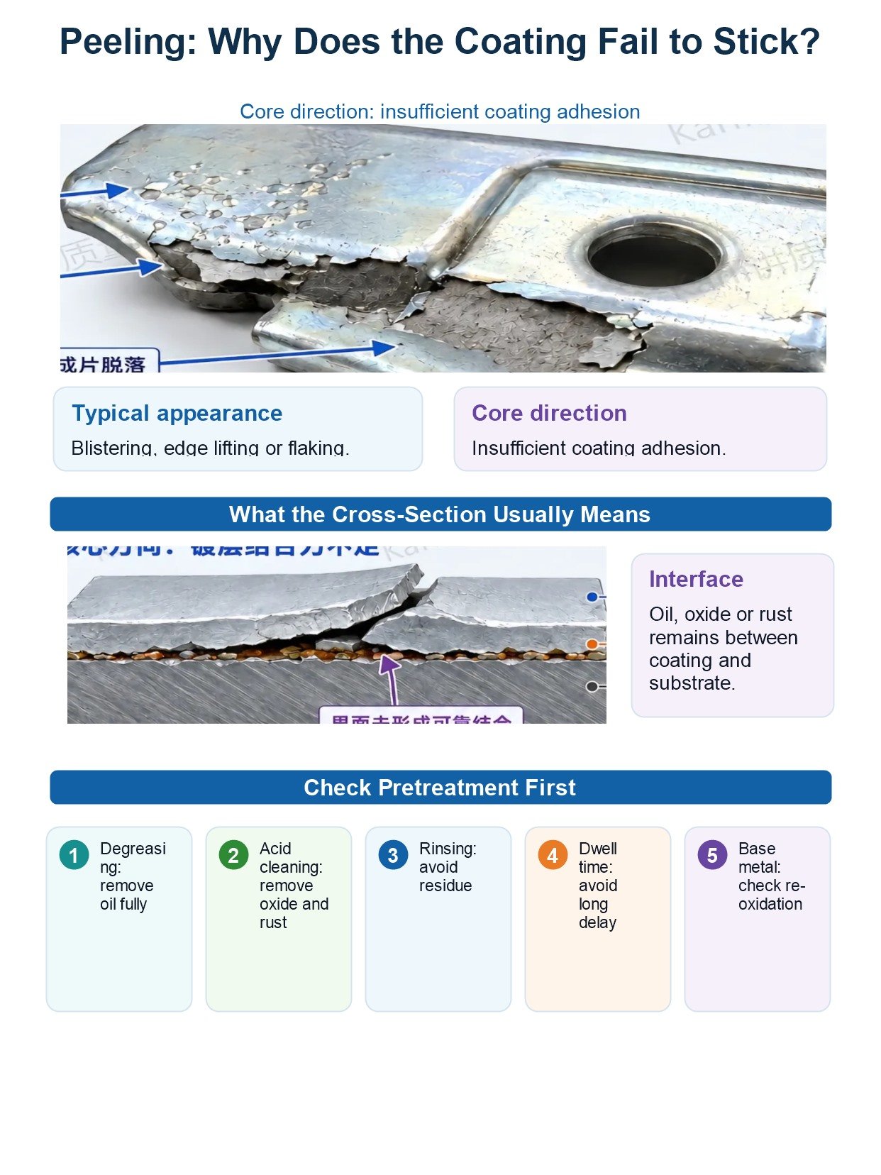
The coating lifts, curls or separates from the substrate. This usually indicates an adhesion failure between the coating and base metal.
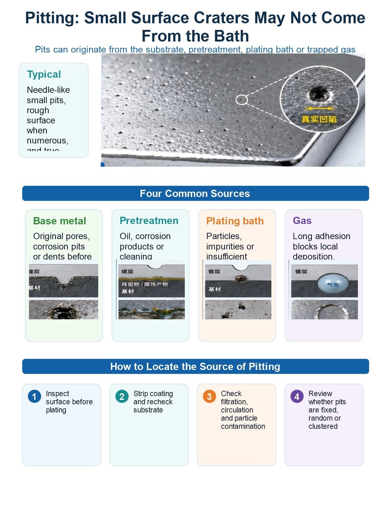
Small dense craters, pinholes or rough spots appear on the surface. The source may be substrate defects, contamination, particles or gas bubbles.
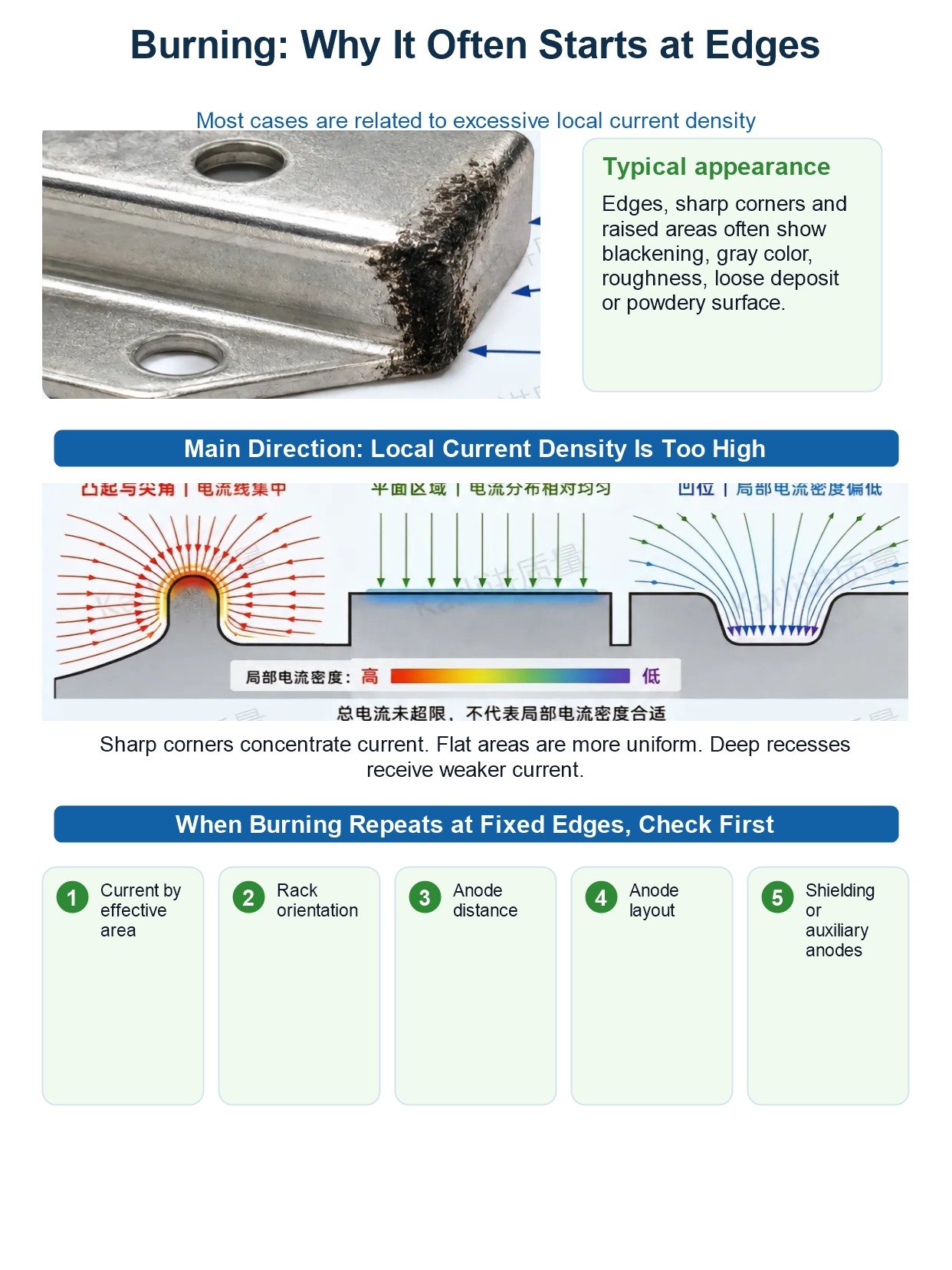
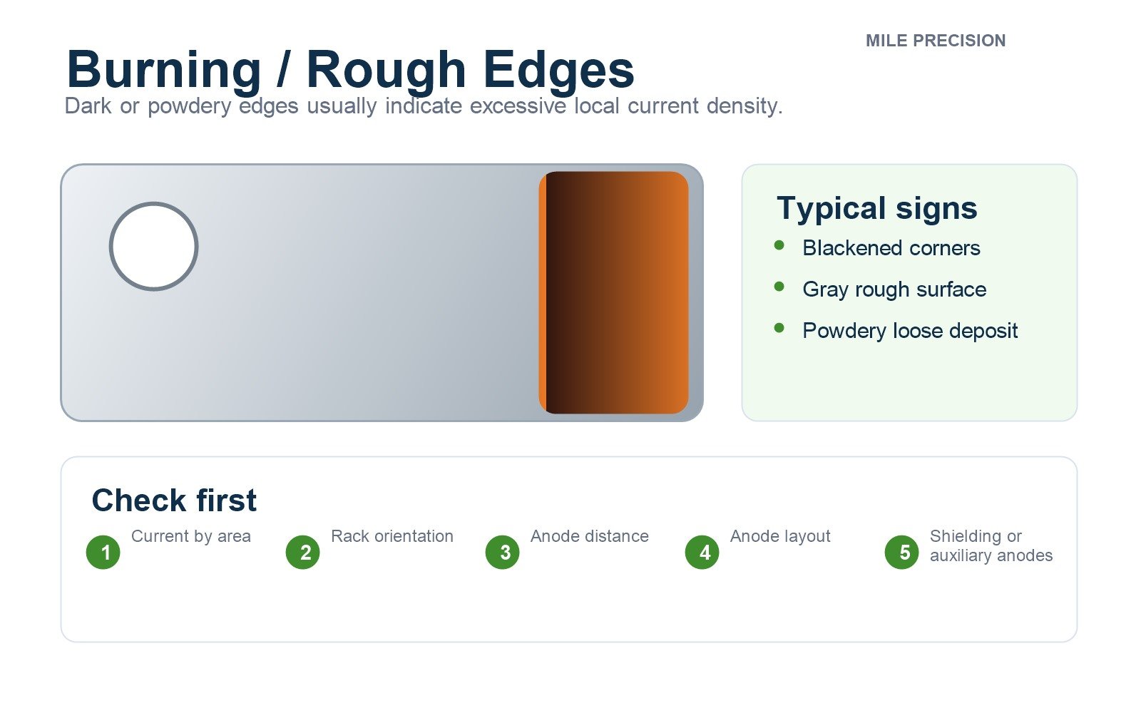
Edges, corners or high-current areas become dark, rough or powdery due to excessive local current density or poor current distribution.
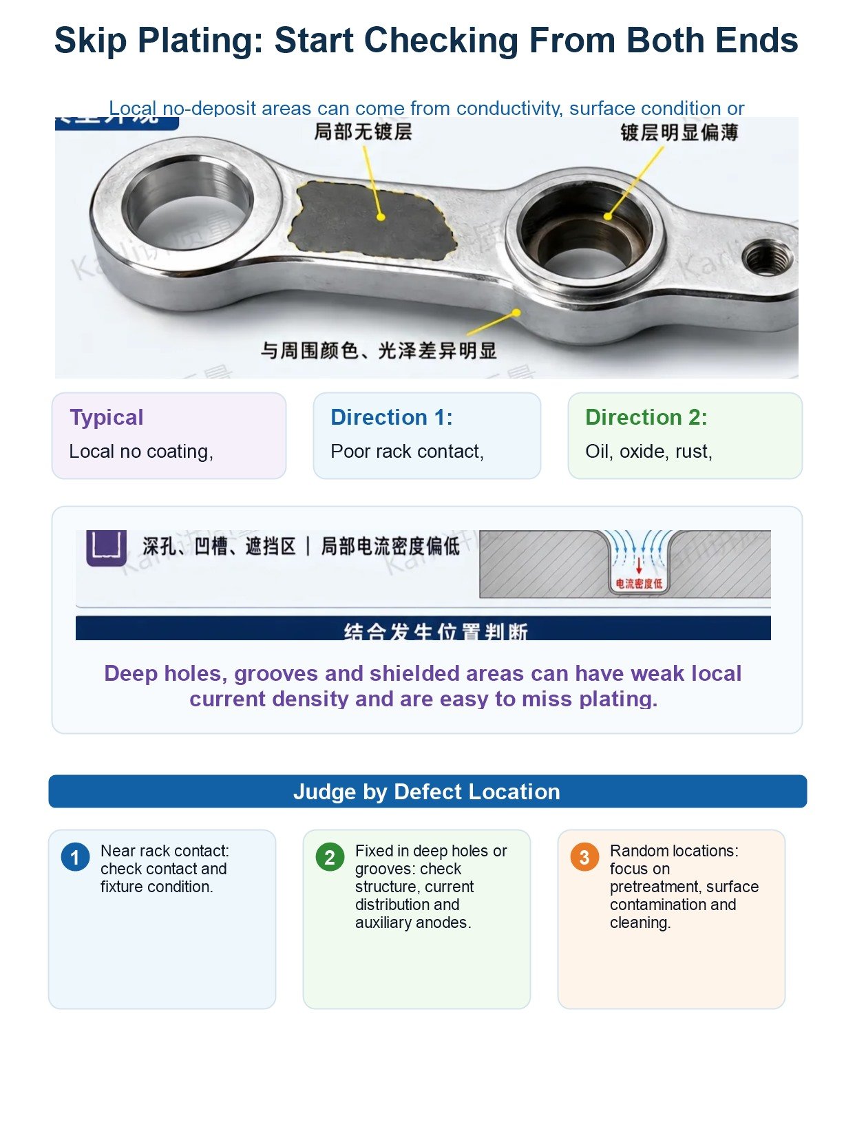
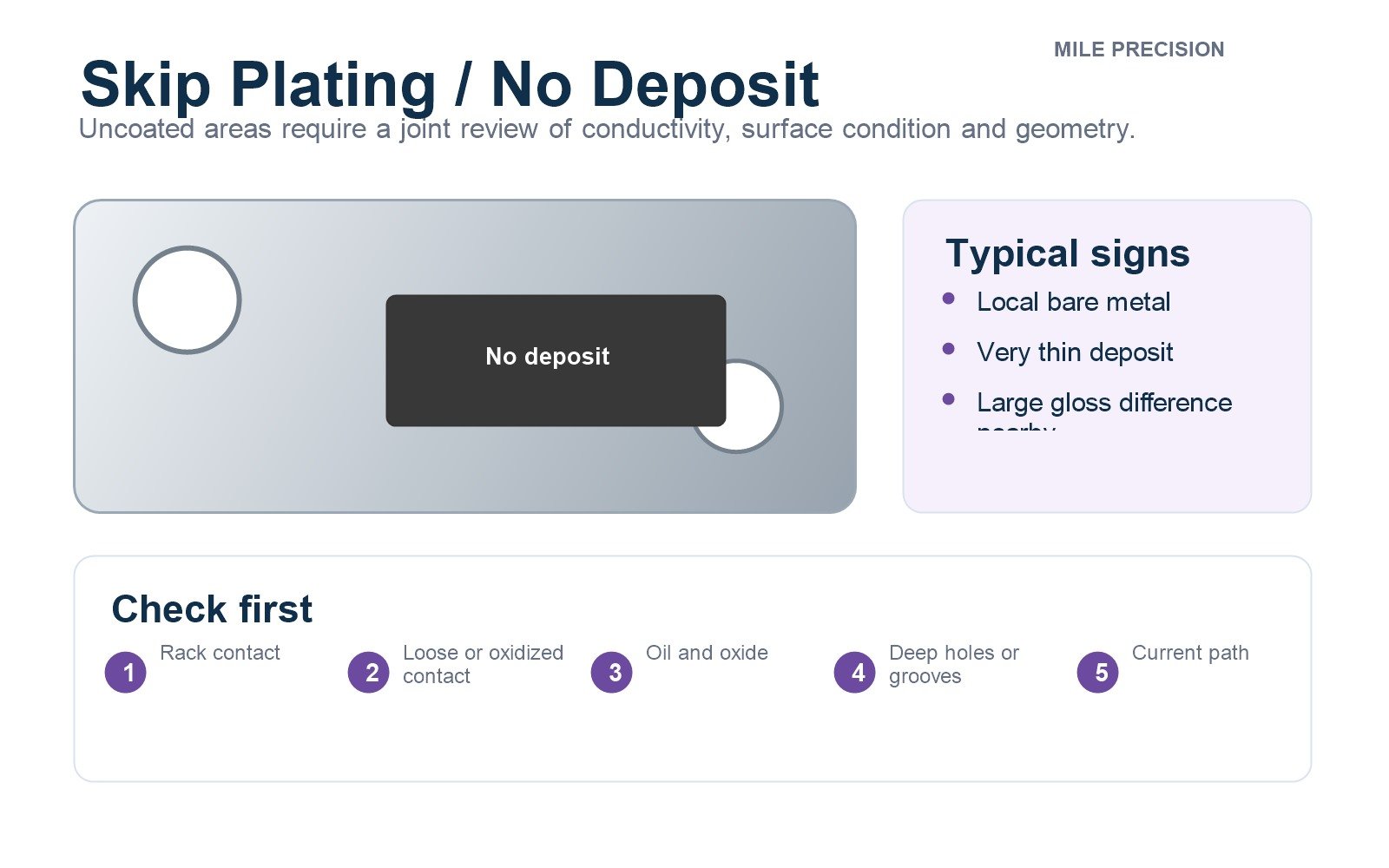
Some areas have little or no coating. Causes may include poor electrical contact, surface contamination, recessed geometry or weak current in shielded zones.
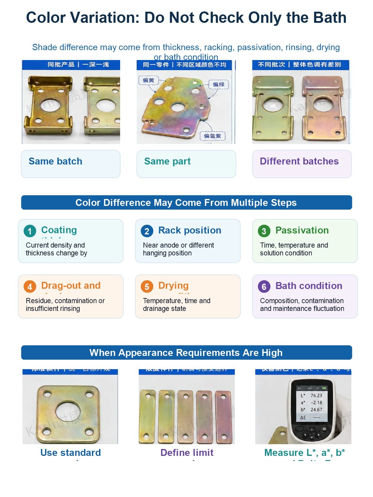
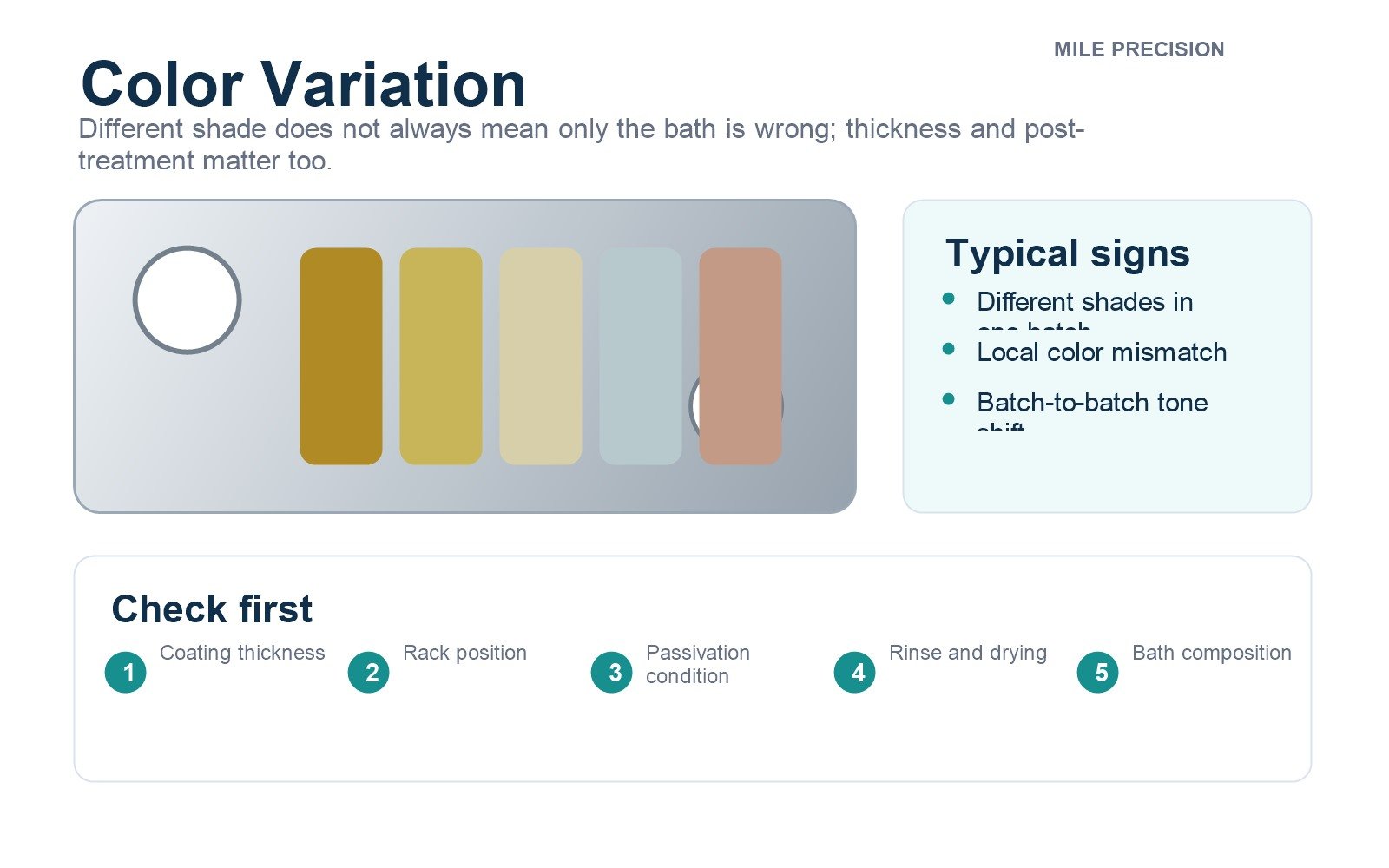
Parts or areas show inconsistent tone, brightness or iridescence. Thickness, passivation, rinsing, drying and bath condition can all affect color.
The coating is too thick in high-current areas and too thin in recessed areas. This is common on complex parts with holes, corners and deep cavities.
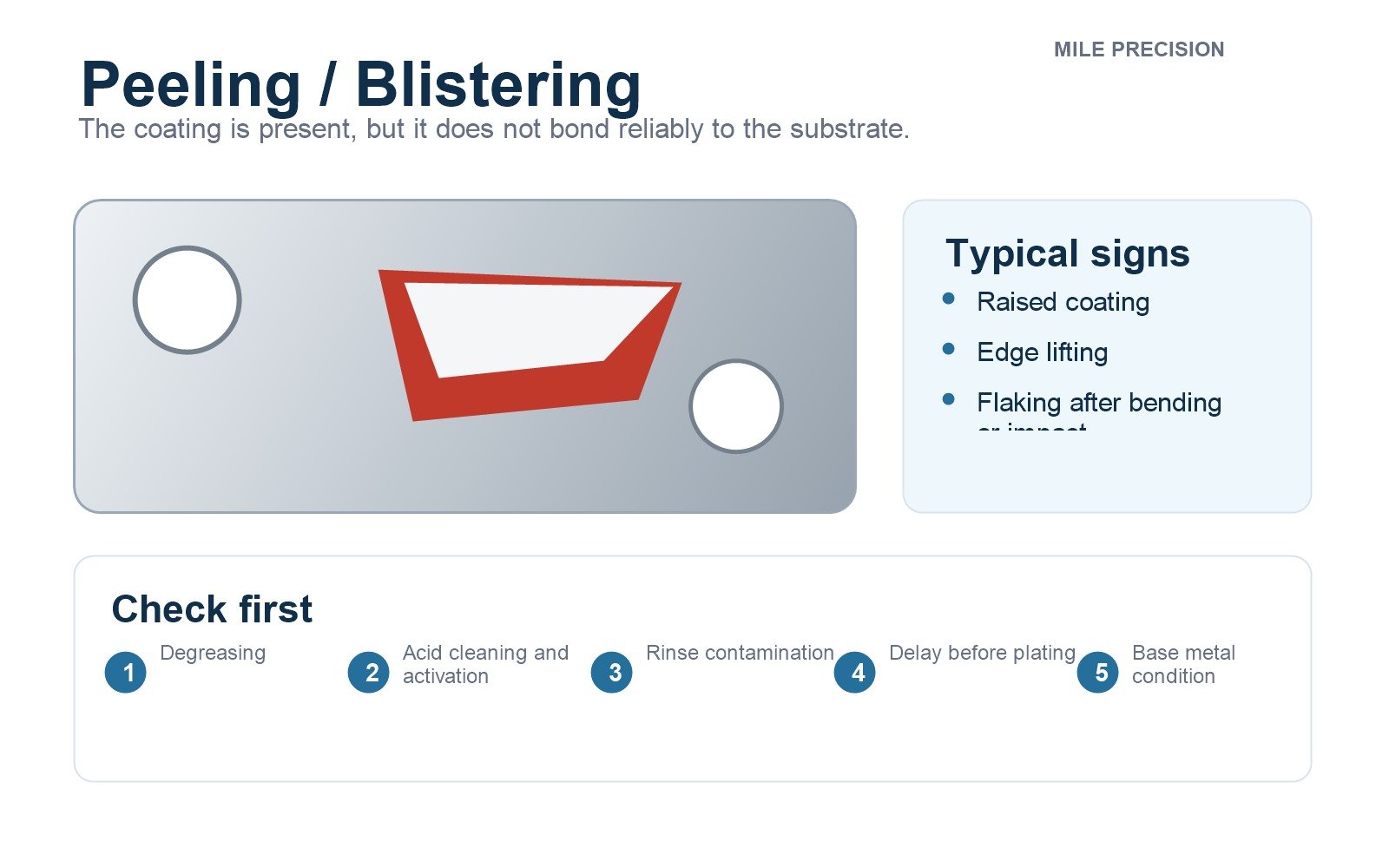
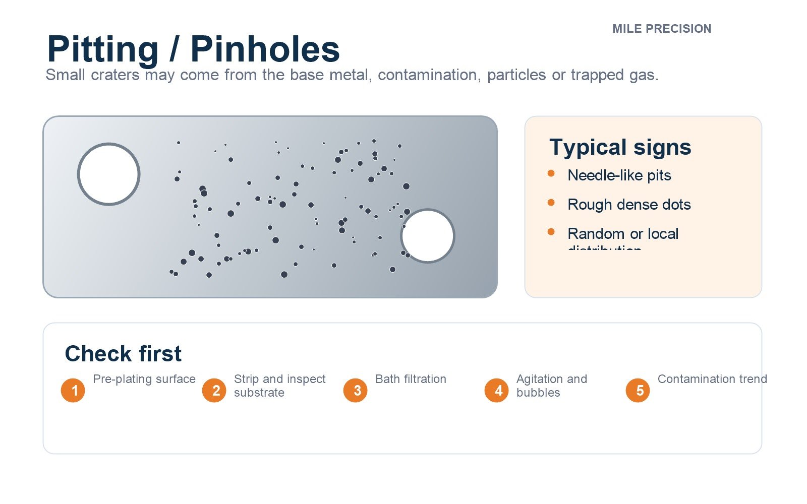
Translated Reference Infographics for 5 Electroplating Defects
The following English infographics are translated and redesigned from the provided reference materials. They combine defect photos, process diagrams and inspection logic so engineers and buyers can review the topic visually.
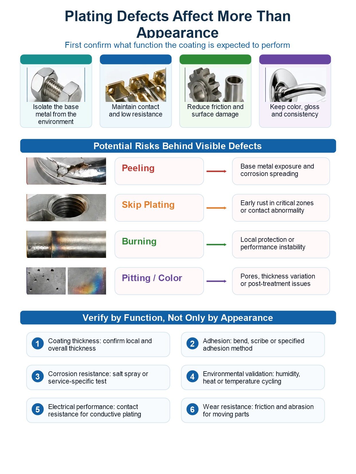
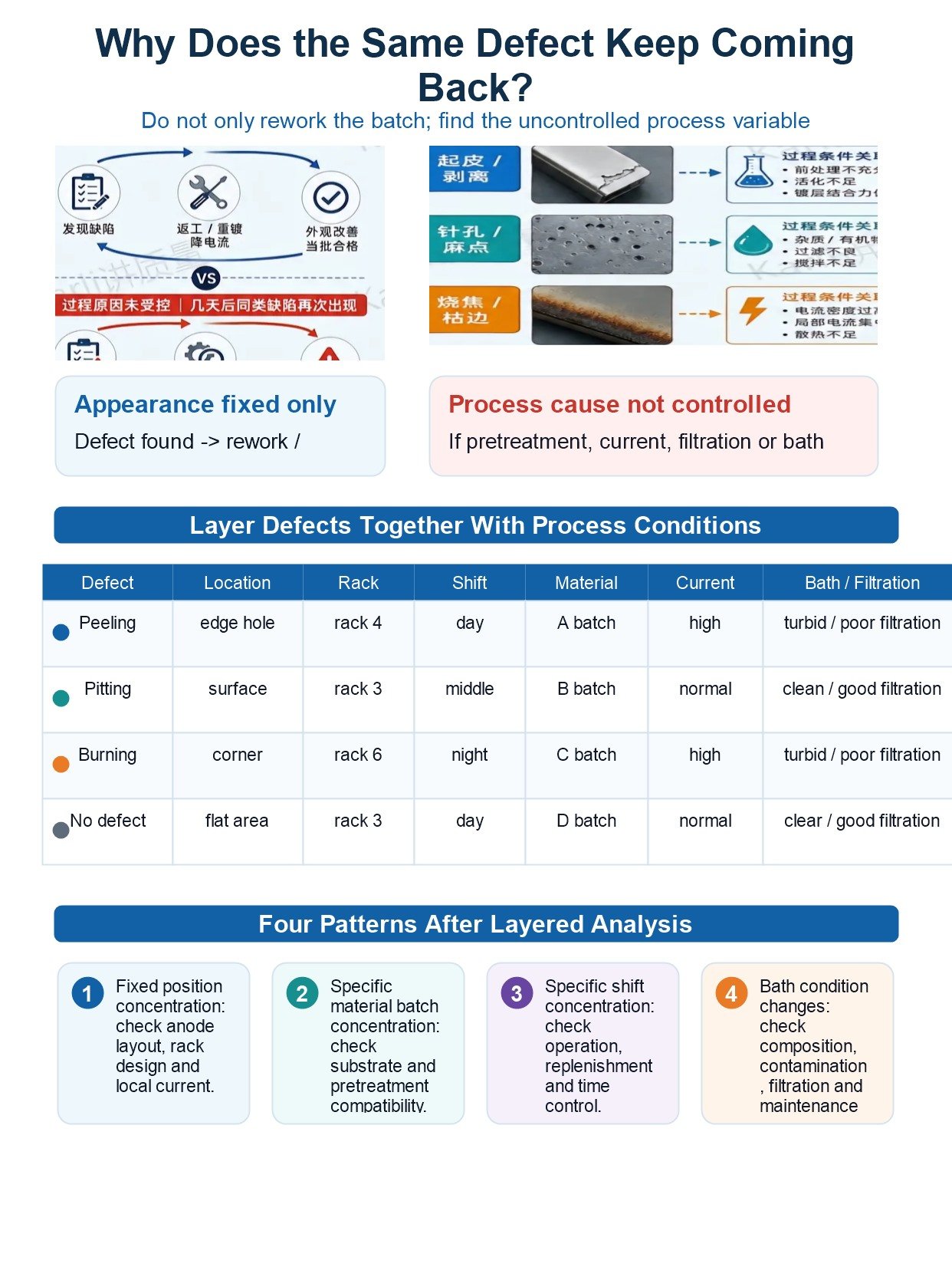
Electroplating Defect Diagnosis Table
Use this table as a practical starting point when reviewing plated parts. It is not a substitute for laboratory testing, but it helps engineers, buyers and suppliers align on what to check first.
| Defect | Typical appearance | Likely process areas | First checks | Potential risk |
|---|---|---|---|---|
| Peeling, blistering or flaking | Raised coating, curled edge, local delamination or sheet-like separation | Degreasing, acid cleaning, activation, oxide removal, substrate condition, excessive delay before plating | Check oil removal, oxide or rust traces, activation time, rinse quality, adhesion test and substrate surface | Base metal exposure, corrosion expansion, early coating failure |
| Pitting or pinholes | Small craters, needle-like holes, rough surface, dense local pits or random pits | Base metal porosity, corrosion pits, bath contamination, poor filtration, particles, organic contamination, gas bubbles | Inspect pre-plating surface, strip coating and recheck substrate, review filtration, agitation and bath cleanliness | Corrosion initiation, appearance rejection, sealing failure on protective coatings |
| Burning or dark rough edges | Blackened corner, gray powdery surface, rough edge, heavy deposit near sharp features | Current density, anode distance, rack orientation, shielding, auxiliary anode design, part geometry | Calculate current by effective area, review high-current edges, check anode layout and use shielding where needed | Low local protection, poor appearance, brittle or powdery deposit |
| Skip plating | Uncoated area, thin coating, dull local spot or visible base metal | Electrical contact, rack mark, surface oil, oxide, deep hole, groove, shielded recess or poor current path | Check rack contact, fixture pressure, contact oxidation, surface cleanliness and current access to recesses | Local corrosion, electrical contact failure, exposed substrate |
| Color variation | Different shade across one part, different color between parts or visible batch-to-batch tone shift | Coating thickness, passivation, rinsing, drying, bath composition, temperature, time and contamination | Use standard samples, define color limits, measure L*a*b* or coating thickness when appearance is critical | Customer rejection, unstable appearance, possible thickness or post-treatment inconsistency |
Main Process Causes Behind Plating Defects
1. Poor surface preparation
Many plating failures start before the part enters the plating bath. Oil, polishing compound, oxide, rust, scale, cutting fluid, passive films and fingerprints can stop the coating from bonding correctly. Even when the fresh coating looks bright, weak adhesion may appear later during bending, impact, assembly or corrosion exposure.
2. Bath contamination or poor filtration
Metal particles, insoluble residue, organic contamination and breakdown products can attach to the part and create pits, roughness or nodules. Filtration, bath analysis and scheduled maintenance are essential, especially for high-volume production where small contamination changes can affect many parts.
3. Unstable current density
Electroplating follows the current path. Sharp edges and outside corners attract more current, while deep holes, grooves and shielded recesses receive less current. Too much current can create burnt, brittle or rough deposits. Too little current can cause thin coating or skip plating.
4. Rack and fixture problems
Racks must hold parts securely and provide reliable electrical contact without creating unacceptable marks. Loose contact, oxidized contact points, inconsistent hanging position or poor part orientation can cause repeat defects in the same location.
5. Rinse, drying and post-treatment variation
Color and brightness are strongly affected by rinsing, passivation, drying and handling. Residual solution, uneven drying temperature or contaminated rinse water may cause stains, water marks, color shift or local corrosion.
How to Prevent Electroplating Defects in Production
Defect prevention starts before plating. For OEM metal parts, the most reliable approach is to connect part design, machining quality, surface preparation, plating control and inspection requirements.
Confirm whether the coating is for corrosion resistance, conductivity, wear resistance, decoration or dimensional build-up.
Identify sharp edges, blind holes, grooves, deep recesses and high-current areas before production.
Verify degreasing, acid cleaning, activation, rinsing and transfer time between steps.
Track rack position, batch, shift, current, bath condition, filtration and defect location.
- Use radius or edge break requirements where sharp corners are not functionally required.
- Specify critical surfaces and non-critical rack contact areas on drawings.
- Agree on coating thickness range and inspection points before mass production.
- Use standard samples or limit samples for decorative finishes and color-sensitive coatings.
- For deep holes and complex geometry, discuss auxiliary anodes, shielding, part orientation and realistic coverage expectations.
- For corrosion-critical parts, validate with neutral salt spray, humidity, adhesion or other tests that match the service environment.
Inspection Methods for Plated Metal Parts
Inspection should match the coating purpose. For decorative parts, visual standards and color limits matter. For functional parts, appearance alone is not enough.
| Inspection item | Purpose | Useful for |
|---|---|---|
| Visual inspection and limit samples | Define acceptable appearance, shade, brightness, stains and visible defects | Decorative zinc, nickel, chrome, black coatings and customer-facing parts |
| Coating thickness measurement | Confirm minimum and maximum coating thickness at defined points | Corrosion-resistant coatings, threaded parts, precision fits and wear surfaces |
| Adhesion testing | Check whether coating bonds to the substrate after bending, cutting, thermal shock or tape testing | Parts exposed to forming, assembly load, vibration or impact |
| Salt spray or corrosion testing | Compare corrosion resistance under a controlled test condition | Zinc plating, nickel plating, passivated finishes and outdoor hardware |
| Electrical resistance or continuity | Confirm conductive performance and contact quality | Terminals, contacts, connectors, busbars and grounding parts |
| Wear or friction testing | Evaluate sliding, abrasion or surface durability | Moving components, shafts, bushings and wear-contact surfaces |
FAQ About Electroplating Defects
Can a defective plated part simply be stripped and replated?
Sometimes yes, but stripping and replating only fixes the visible part if the root cause is corrected. If the cause is poor pretreatment, bath contamination, fixture contact or current distribution, the same defect may return.
Why do plating defects often appear at edges and corners?
Edges, corners and raised features often receive higher local current density. This can create heavy, rough or burnt deposits. Deep recesses and holes may receive lower current and become thinly plated or unplated.
Why are there pits after plating?
Pits may already exist in the substrate, or they may be caused by particles, bath contamination, trapped gas, poor cleaning or corrosion products. Stripping the coating and checking the base surface helps separate substrate defects from plating-process defects.
How can buyers reduce electroplating problems on custom metal parts?
Share drawings with critical surfaces, coating function, thickness requirements, appearance limits and service environment. For complex parts, review racking, current access, edge radius, blind holes and inspection standards before production.
Need Custom Metal Parts With Controlled Surface Finishing?
Milemetal supports CNC machining, metal fabrication and surface finishing coordination for OEM parts. Send your drawing, material, finish requirement and target application for review.
Reference: This article was informed by practical plating defect analysis and the electroplating defect overview from Sharretts Plating. Content has been rewritten and expanded for OEM metal parts and Milemetal production discussions.